If you’re working on seepage control for a dam, levee, or cofferdam, you’ll need actual numbers—exit gradients, uplift pressures, flow rates, and seepage forces—before you can judge whether you have a real stability problem or not. This Seepage Force Flow Net Calculator lets you put in your flow net values—head difference, flow channels, equipotential drops, permeability, and unit weights—to get the numbers most needed for practical design. Underestimating exit gradient can be a critical error in earth dam or excavation support work; once piping starts, it’s hard to stop with patchwork fixes. On this page you’ll find governing equations, a direct worked example for a cofferdam, the key engineering background, and an FAQ that covers useful edge cases and real-world limitations.
What is Seepage Force Flow Net Analysis?
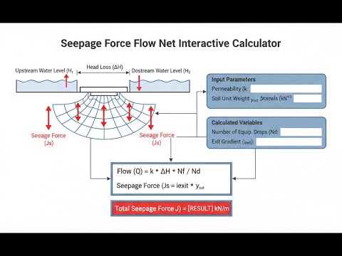
A flow net is a simple but effective way to estimate water flow and pressure through soil under a hydraulic structure. By sketching flow lines (water paths) and equipotential lines (locations at equal pressure), you get a grid you can count. Those counts, along with site characteristics, let you calculate seepage rates, gradients—including at the most vulnerable exit—and the pressures acting on the structure and soil. The approach is straightforward and widely used in practical geotechnics.
Simple Explanation
When water moves under a dam, not all routes carry equal flow—just like not all lanes in a road network handle the same traffic. A flow net is a map of how water takes these different paths (flow lines), and where the pressure drops (equipotential lines, acting like checkpoints). Where these checkpoints get packed close together near the exit, that’s where the soil is most at risk for being washed out (piping), which is where you focus design effort.
📐 Browse all 1000+ Interactive Calculators
Flow Net Diagram

Interactive Seepage Force Flow Net Calculator
How to Use This Calculator
This calculator is intended for education, concept evaluation, and preliminary design. Results are based on the equations and assumptions described on this page, but cannot account for every real-world load case, tolerance, material property, environmental condition, installation detail, safety factor, code, or regulatory requirement. Verify all inputs, assumptions, units, and results independently before selecting components or using the result in a real application. Safety-critical, structural, medical, lifting, transportation, or regulated applications must be reviewed by a qualified engineer.
- Select your calculation mode from the dropdown — choose from seepage force, exit gradient, flow rate, uplift pressure, factor of safety, or head loss.
- Enter the total head difference (H), number of flow channels (Nf), number of equipotential drops (Nd), and unit weight of water. Enter additional inputs (permeability, soil unit weight, specific gravity, void ratio, exit length, or flow length) if your selected mode requires them.
- If you want to run a quick test, click Try Example to populate all fields with a representative set of values.
- Click Calculate to see your result.
Seepage Force Flow Net Interactive Calculator
Adjust flow net parameters like channels, head, and soil properties and see how key seepage values react—exit gradient, flow rate, and safety factors update in real time as you tweak the numbers. This is a practical way to get a feel for sensitivity in these sorts of problems.
EXIT GRADIENT
0.67
FLOW RATE
6.7 L/h
SAFETY FACTOR
1.49
FIRGELLI Automations — Interactive Engineering Calculators
Governing Equations
Use the formula below to calculate the flow net shape factor.
Flow Net Shape Factor
Shape Factor = Nf / Nd
Where:
- Nf = Number of flow channels (dimensionless)
- Nd = Number of equipotential drops (dimensionless)
Use the formula below to calculate seepage discharge.
Seepage Discharge (Flow Rate)
q = k × H × (Nf / Nd)
Where:
- q = Seepage discharge per unit width (m³/s/m)
- k = Coefficient of permeability (m/s)
- H = Total head difference (m)
Use the formula below to calculate hydraulic gradient.
Hydraulic Gradient
i = Δh / Δl = H / Nd
Where:
- i = Hydraulic gradient (dimensionless)
- Δh = Head loss between equipotential lines (m)
- Δl = Flow path length between equipotential lines (m)
Use the formula below to calculate seepage force per unit volume.
Seepage Force per Unit Volume
j = γw × i
Where:
- j = Seepage force per unit volume (kN/m³)
- γw = Unit weight of water (typically 9.81 kN/m³)
Use the formula below to calculate exit gradient.
Exit Gradient
ie = H / (Nd × Le / Nf)
Where:
- ie = Exit gradient at downstream face (dimensionless)
- Le = Length of exit face (m)
Use the formula below to calculate critical hydraulic gradient.
Critical Hydraulic Gradient
ic = (Gs - 1) / (1 + e)
Where:
- ic = Critical hydraulic gradient causing piping (dimensionless)
- Gs = Specific gravity of soil solids (dimensionless)
- e = Void ratio (dimensionless)
Use the formula below to calculate factor of safety against piping.
Factor of Safety Against Piping
FS = ic / ie
Design Criterion: FS ≥ 3.0 for safe design, FS ≥ 4.0 for critical structures
Simple Example
Given: H = 5 m, Nf = 4, Nd = 10, k = 0.00002 m/s, γw = 9.81 kN/m³.
Hydraulic gradient: i = 5 / 10 = 0.50
Seepage force per unit volume: j = 9.81 × 0.50 = 4.91 kN/m³
Seepage discharge: q = 0.00002 × 5 × (4/10) = 4.0 × 10⁻⁵ m³/s/m
Theory & Engineering Applications
Flow nets are a hands-on, visual method for solving steady-state seepage in 2D problems. They go back to Casagrande in the 1930s and work by sketching two curves: flow lines (paths water takes) and equipotential lines (places at the same total head). This method makes it simple to estimate pore pressures, seepage rates, and the main risks without heavy numerical calculation.
Flow Net Construction Principles and Mathematical Foundation
To be usable, a flow net must follow Laplace's equation (∇²h = 0), which applies to steady-state seepage in isotropic soils. The critical thing is that flow lines and equipotential lines cross at right angles, forming near-squares—not rectangles or random quadrilaterals. This layout reflects the boundary conditions: water faces at each end, usually an impermeable layer at the bottom, and the structure in between. More channels or more drops doesn’t change the shape factor (Nf/Nd), so you can refine the sketch without affecting the main results. In most jobs, 4–6 channels gives a reasonable answer. If you can get curvilinear squares and orthogonal crossings, you’ve got something suitable for use.
Critical Non-Obvious Limitation: Anisotropic Soil Behavior
Not all soils act the same in every direction. In most real ground, horizontal permeability (kh) is higher than vertical (kv), because layering is common. Basic flow nets assume isotropy, and using them as-is in layered or anisotropic soils can give very inaccurate answers. The standard adjustment is to scale the vertical dimension by √(kh/kv) before drawing the net, then scale any vertical measurements back when reading off real-world values. For example, if kh/kv is 4, halve the vertical scale. This approach isn’t usually shown in textbooks but is necessary for real projects where soil stratification is the norm.
Exit Gradient Analysis and Piping Failure Prevention
Exit gradient is usually the most critical number when you’re worried about piping. If the upward water force exceeds the submerged weight of the soil, the soil behaves like a liquid and can be carried away—quick condition. The threshold (critical gradient, ic) normally sits between 0.9 and 1.1 for sandy soils, found from ic = (Gs - 1)/(1 + e). Codes require a substantial margin (factor of safety usually 3 or more, sometimes 4 for critical structures), because failures here are sudden. The worst gradient, and where failures start, is right at the downstream toe where flow converges and equipotential lines crowd. Practical measures include adding drainage filters, berms, or extending the cutoff to reduce this gradient. Filters, in particular, let water escape but keep soil grains in place—an old but reliable technique for exit control.
Comprehensive Worked Example: Sheet Pile Cofferdam Analysis
Suppose you have a sheet pile cofferdam, 8.7 meters deep, through uniform sand for bridge work. There’s a 5.4-meter water level difference between inside and outside. The sand has k = 2.3 × 10⁻⁵ m/s, γsat = 19.2 kN/m³, Gs = 2.68, void ratio e = 0.63. Counting the flow net, you get 4.5 flow channels and 13 drops. Here’s how you work through it:
Step 1: Calculate Shape Factor and Seepage Discharge
Shape factor: Nf/Nd = 4.5/13 = 0.346
Discharge per meter: q = k × H × (shape factor) = 2.3 × 10⁻⁵ × 5.4 × 0.346 = 4.30 × 10⁻⁵ m³/s/m
For a 24 meter-long cofferdam: Qtotal = 4.30 × 10⁻⁵ × 24 = 1.032 × 10⁻³ m³/s ≈ 89.2 m³/day
You’ll want to size the pumps for something higher—about 120 m³/day—to cover normal variability and keep things dry.
Step 2: Determine Exit Gradient
The last equipotential drop at the toe happens over a segment of around 2.1 meters (measured off the diagram).
Exit gradient: ie = 5.4 / (13 × 2.1 / 4.5) = 5.4 / 6.067 = 0.890
This is high—above what’s typically tolerated.
Step 3: Calculate Critical Gradient and Factor of Safety
ic = (2.68 - 1)/(1 + 0.63) = 1.68/1.63 = 1.031
FS = ic / ie = 1.031 / 0.890 = 1.16
Bottom Line: Factor of safety here is much too low. Solutions: drive piles deeper, add a downstream berm for weight, or install relief wells to intercept water before it builds high gradients at the exit.
Step 4: Calculate Uplift Pressure Distribution
Head loss per drop: Δh = 5.4 / 13 = 0.415 m
At the sheet pile toe (after 6 drops from upstream): htoe = 5.4 - (6 × 0.415) = 2.91 m
Uplift at toe: utoe = 9.81 × 2.91 = 28.5 kPa
Max uplift (upstream face): umax = 9.81 × 5.4 = 53.0 kPa
Average uplift force per m (over 24 m length): Fuplift = (53.0 + 0) / 2 × 24 = 636 kN/m
This requires significant weight—usually a 0.8–1.0 m thick concrete slab is specified—to keep the slab from lifting.
Applications in Dam and Levee Engineering
Seepage flow nets drive the basics of dam and levee seepage design. For earth dams, the top flow line (phreatic surface) tells you how much of the structure is saturated, which is key to slope stability and how high water can safely go. Cutoff trenches, drains, and filter design all rely on reading gradients off a flow net. Proper cutoffs and drainage can lower pore water pressures by almost half, making the entire dam far less likely to fail.
For concrete dams, the uplift pressure diagram (from the flow net) sets minimum weight and geometry—get it wrong and the dam could slide. Adding a drainage gallery reduces uplift loads, splitting the seepage path and typically cutting pressures by a good margin—sometimes 30-50%—without any heroic construction methods.
Sheet Pile Wall and Excavation Applications
Temporary sheet pile walls make dewatering and undercut work possible, but can also bring seepage and base heave if not checked. Flow nets help you size penetration depth, pump rates, and where you’ll need dewatering wells or thickening at the base. In urban sites, ground loss from poor control can damage adjacent buildings. Permanent waterfronts have the opposite problem: long-term seepage needs to be managed without washing away soil, so graded filter and drainage designs are made directly from the flow net results, rather than relying just on rules of thumb or historical experience.
Always remember: flow nets work for steady-state (not time-varying) conditions and uniform soils. As soon as you’re in layered soils or anything not resembling a simple rectangle, hand flow nets provide a starting point—but a finite element analysis or numerical software is often needed for final checks on anything critical. Still, a flow net gets to the basic physics fast, gives a reality check before heavy analysis, and is a good way to catch gross errors or design oversights early.
Practical Applications
Scenario: Dam Safety Assessment Following Heavy Rainfall
After several weeks of heavy rain, a downstream increase in seepage is noticed at an older earth dam. With a head difference of 7.3 meters, 6 flow channels, 14 drops, and soil parameters straight from old construction records, an exit gradient of 0.86 and a safety factor of 1.15 are calculated. This is too low. The team responds by lowering reservoir level, adding temporary relief wells, and planning a downstream berm and drainage blanket to push the safety factor up to at least 3.0 before the next storm.
Scenario: Urban Excavation Dewatering Design
For an urban basement dig—12 m deep, tight site, sensitive neighboring foundations—a dewatering calculation using the flow net arrives at a needed pumping capacity of about 206 m³/day with a safety margin, and a calculated base exit gradient giving FS = 2.47. The design is modified to include a thick sand ballast under the excavation to lower heave risks for the construction duration.
Scenario: Levee Upgrade Cost-Benefit Analysis
When comparing three levee upgrade strategies—cutoff wall, downstream berm, or drainage blanket—the flow net calculator quickly shows that while the cutoff wall has the best safety improvement, it’s also the most expensive. After reviewing exit gradients, factors of safety, and seepage for each case, the downstream berm with a high-spec filter is picked as the best compromise for budget and performance in this specific municipal flood control project.
Frequently Asked Questions
How do I determine the correct number of flow channels and equipotential drops for my flow net? +
What factor of safety against piping should I use for different types of hydraulic structures? +
How do I handle layered soil deposits with different permeabilities in flow net analysis? +
What's the difference between average gradient and exit gradient, and why does it matter? +
How accurate are flow net calculations compared to finite element seepage analysis? +
What remedial measures can reduce exit gradients if my calculated factor of safety is too low? +
Free Engineering Calculators
Explore our complete library of free engineering and physics calculators.
Browse All Calculators →🔗 Explore More Free Engineering Calculators
About the Author
Robbie Dickson — Chief Engineer & Founder, FIRGELLI Automations
Robbie Dickson brings over two decades of engineering expertise to FIRGELLI Automations. With a distinguished career at Rolls-Royce, BMW, and Ford, he has deep expertise in mechanical systems, actuator technology, and precision engineering.
Need to implement these calculations?
Explore the precision-engineered motion control solutions used by top engineers.


