Designing AC circuits with resistors, inductors, and capacitors comes down to controlling impedance — a value that shifts with frequency. Getting the numbers wrong usually leads to circuits that don’t do what you want: a filter that doesn’t cut enough, a resonant trap that misses its mark, or a power section that runs too hot. This RLC Impedance Interactive Calculator is here to give you the total impedance, phase angle, resonance point, Q factor, power factor, and bandwidth from your values of resistance, inductance, capacitance, and frequency. These calculations aren’t academic — they’re used for tuning filters, building RF matching networks, and correcting industrial power factor, basically anywhere the frequency response of your circuit matters. Below, you’ll find the key formulas, a step-by-step example, details on both series and parallel circuit behavior, and a practical FAQ for day-to-day engineering questions.
What is RLC impedance?
RLC impedance is the combined opposition to AC current in a circuit that includes resistance (R), inductance (L), and capacitance (C). Unlike pure resistance, the impedance changes depending on frequency — which is why you can use RLC circuits for tuning, filtering, or AC power correction.
Simple Explanation
Picture a plumbing system, where resistance is like pipe width, a spring (the capacitor) resists rapid changes, and a flywheel (the inductor) resists starting and stopping. How strongly they push back depends on how fast the pressure changes — that is, the frequency. There's one frequency where the spring and flywheel effects cancel each other, and that's the resonance point. Most practical RLC design is about targeting or avoiding that point.
📐 Browse all 1000+ Interactive Calculators
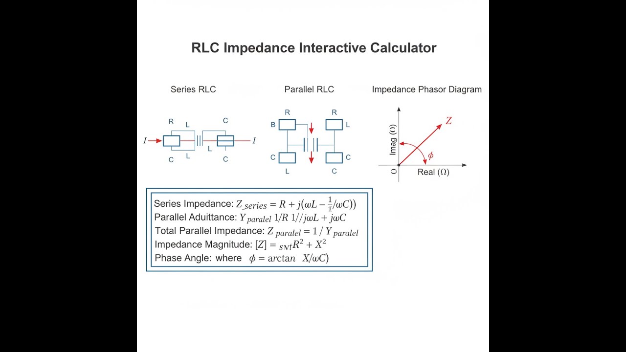
RLC Circuit Diagrams

RLC Impedance Calculator
How to Use This Calculator
This calculator is intended for education, concept evaluation, and preliminary design. Results are based on the equations and assumptions described on this page, but cannot account for every real-world load case, tolerance, material property, environmental condition, installation detail, safety factor, code, or regulatory requirement. Verify all inputs, assumptions, units, and results independently before selecting components or using the result in a real application. Safety-critical, structural, medical, lifting, transportation, or regulated applications must be reviewed by a qualified engineer.
- Select the calculation mode — Series RLC, Parallel RLC, Resonant Frequency, Q, Power Factor, or Bandwidth.
- Enter your resistance (Ω), inductance (mH), and capacitance (μF).
- Enter the frequency (Hz), unless you’re solving for resonance.
- Click Calculate and check the answer.
RLC Impedance Interactive Visualizer
Adjust the resistance, inductance, capacitance, and frequency to see how impedance and phase angle behave. You’ll notice the biggest changes when you sweep across the resonance point.
IMPEDANCE |Z|
100 Ω
PHASE ANGLE
0°
RESONANCE
1006 Hz
FIRGELLI Automations — Interactive Engineering Calculators
RLC Impedance Equations
Below are the core formulas used to determine reactance for each component.
Reactance Components
XL = ωL = 2πfL
XC = 1/(ωC) = 1/(2πfC)
XL = Inductive reactance (Ω)
XC = Capacitive reactance (Ω)
ω = Angular frequency (rad/s)
f = Frequency (Hz)
L = Inductance (H)
C = Capacitance (F)
And here are the forms for total series and parallel RLC impedance:
Series RLC Impedance
Z = R + j(XL - XC)
|Z| = √(R² + (XL - XC)²)
φ = arctan((XL - XC)/R)
Z = Complex impedance (Ω)
R = Resistance (Ω)
φ = Phase angle (degrees or radians)
j = Imaginary unit (√-1)
Here’s the formula set for admittance and resulting impedance in parallel RLC circuits:
Parallel RLC Admittance
Y = 1/R + j(1/XC - 1/XL)
|Y| = √((1/R)² + (1/XC - 1/XL)²)
Z = 1/Y
Y = Complex admittance (S)
G = 1/R = Conductance (S)
B = 1/XC - 1/XL = Susceptance (S)
For resonance and quality factor calculations, use:
Resonance & Quality Factor
f0 = 1/(2π√(LC))
Qseries = ω0L/R = 1/(ω0RC)
BW = f0/Q
f0 = Resonant frequency (Hz)
Q = Quality factor (dimensionless)
BW = Bandwidth at half-power points (Hz)
Simple Example
For a series RLC at 1000 Hz, with R = 100 Ω, L = 10 mH, and C = 2.533 μF, you get:
- Inductive reactance XL = 2π × 1000 × 0.01 = 62.83 Ω
- Capacitive reactance XC = 1 / (2π × 1000 × 0.000002533) = 62.83 Ω
- Net reactance X = 62.83 − 62.83 = 0 Ω (resonance)
- Total impedance |Z| = √(100² + 0²) = 100 Ω, phase angle = 0°
Theory & Practical Applications of RLC Impedance
If you’re working with RLC circuits, the key thing is their impedance always depends on frequency. Pure resistance is easy — it doesn't vary. Both inductors and capacitors, however, store energy as fields (magnetic for L, electric for C) and return it later, so the total opposition they add to the circuit changes as the frequency changes. This trait is what lets engineers build tuned filters, match impedances in RF, and improve power system performance. If you need to know what happens across frequencies, you need both magnitude and phase — not just the value, but the angle between current and voltage, usually handled with complex numbers or phasors.
Series vs. Parallel RLC Configuration Behavior
Series RLC circuits reach their lowest impedance at resonance, because the inductor and capacitor reactances cancel out (XL = XC), so you’re left with just the resistance. Maximum current happens here. Go below resonance and the circuit starts acting capacitive — current leads voltage. Above resonance, it shifts inductive and current lags voltage. This is why series RLCs are used for bandpass filtering and places where you want peak current at one frequency.
Parallel RLC circuits act the other way — at resonance, their impedance is at its peak, not its minimum. You get Zmax instead of Zmin. This tank circuit effect (energy bounces between L and C) is common in oscillators and RF circuits where you want high voltage swing at a very specific frequency and low impedance for harmonics. In practical circuits, the impedance peak is sometimes orders of magnitude higher than any of the branch resistances, especially if your parts are ideal, but most real parts aren’t.
Quality Factor and Bandwidth Relationships
Q (quality factor) measures how well a circuit stores energy compared to how much it loses per cycle. For series RLC, high Q means a sharp resonance and a narrow passband. You use high-Q circuits for making sharp filters, like radio receivers with good channel selectivity. Bandwidth equals f0/Q, so a Q of 50 at 455 kHz means your -3dB filter bandwidth is about 9 kHz — just enough for AM audio, barely letting through the 5 kHz wanted and cutting off adjacent 10 kHz channels.
But there are limits. Inductors have real resistance (wire resistance, core losses), and capacitors have some loss too (ESR and dielectric loss). These losses lower the maximum usable Q — you rarely get more than a few hundred at RF, even with excellent components. Also, high-Q circuits are extremely sensitive to part tolerances: change your C by 5% in a Q 100 circuit and you can miss resonance by more than 2%, enough to miss a whole FM channel or radio IF passband if you’re unlucky. This is why real-world filters often use cascaded stages of lower-Q circuits — you trade some sharpness for predictability in manufacturing.
Impedance Transformation and Matching Networks
RLC matching networks adjust source and load impedances to get the most power through at a chosen frequency. L-matches use just one L and one C, arranged so they can adapt nearly any two resistances to each other, but only at one frequency. If you need, say, to go from 50Ω to 200Ω at 100 MHz, you determine the reactance each side needs, then translate those into values for L and C. The practical part is these matches only work for one frequency at a time, and all practical reactances have their own Q limitations.
T- and pi-networks expand the idea: you can adjust them for more ratio options and broader responses (wider bandwidths). Pi-networks are common in RF amplifiers for this reason — you get both impedance transformation and some filtering against harmonics. But as you make the Q lower for more bandwidth, you lose harmonic suppression, so it’s always a compromise between efficiency, filtering, and bandwidth.
Power Factor Correction in AC Systems
Most industrial AC systems lag in power factor (common for sites with lots of motors, big transformers, or fluorescent lights). If you don’t correct it, you waste current and heat; current goes up for the same real power, increasing losses. Installing shunt capacitors is a standard fix, bringing the power factor closer to 1. To get this right, you need to size the caps for your actual reactive power — so if your real load is 100 kW at 0.8 power factor, you’re moving about 75 kVAR of useless current; add 75 kVAR of capacitors to counteract it. But if you overdo it with too much capacitance, you risk over-correcting, getting leading power factor, or even hitting resonance with the supply’s natural inductance. That’s why most cap banks are switched in steps and sometimes include harmonic filters to prevent dangerous resonances.
Capacitor banks must also account for harmonics, especially with modern electronics. Harmonics and capacitors can interact badly, so real systems add reactors tuned below key harmonics to avoid amplifying unwanted frequencies.
Practical Worked Example: Designing a 10.7 MHz IF Filter
For an FM radio IF you need: center at 10.7 MHz, 200 kHz bandwidth, 50Ω in/out, use a 1 μH inductor (QL = 80).
- Calculate capacitance: C = 1/(4π²f₀²L) ≈ 220 pF.
- Find inductor’s resistance: XL ≈ 67.23Ω, so RL = XL/Q = 0.840Ω.
- Loaded Q for bandwidth: Qloaded = 10.7M/200k = 53.5.
- Total needed series resistance: Rtotal = XL/Q = 1.257Ω, so add 0.417Ω externally.
- Use a tapped inductor or capacitive divider to match 1.257Ω to 50Ω; a tap at about 16% works.
- Check insertion loss (mainly from Q) — it's about 0.5 dB, and the filter provides acceptable -3dB bandwidth and adjacent-channel attenuation.
That’s the typical process for practical IF filter design: check calculated values, factor in part losses, design tap or matching for a standard system impedance, and verify you really get the selectivity required at real-world tolerances.
Skin Effect and High-Frequency Impedance Behavior
At high frequency, current moves to the surface of the conductor (skin effect), so resistance goes up as frequency rises. For example, copper at 10 MHz has a skin depth of 21 μm; at 1 GHz, it's down to 2.1 μm. This means a thick wire doesn't help anymore — almost all current flows in the outer skin. Your inductor Q drops fast, and in practice you end up using litz wire (for HF), or hollow tubes or PCB traces (for VHF/UHF), to keep losses reasonable.
All wires and component leads have parasitic inductance and capacitance. At some frequency, you’ll hit a spurious resonance (the self-resonance of the part) and your capacitor may start acting more like an inductor. For RF work, you need to look up the self-resonant frequency in the datasheet — or better yet, measure the real part in-circuit. Surface-mount parts help by keeping leads short, and for the most precise work, full S-parameter data trumps textbook RLC models.
For more detail on AC circuits and impedance, check out the main engineering calculator library.
Frequently Asked Questions
▼ Why does impedance in series RLC circuits reach minimum at resonance while parallel circuits reach maximum?
▼ How do component tolerances affect RLC circuit resonant frequency and bandwidth in practical applications?
▼ What causes the power factor to differ from unity in RLC circuits, and why does this matter for power systems?
▼ How does skin effect limit inductor Q at high frequencies, and what design techniques compensate for this limitation?
▼ Why do impedance matching networks often use reactive elements exclusively, and when must resistive elements be included?
▼ What physical mechanisms limit the maximum achievable Q in practical LC resonators, and how do engineers work around these limits?
Free Engineering Calculators
Explore our complete library of free engineering and physics calculators.
Browse All Calculators →— - Explore More Free Engineering Calculators
- Resistor Color Code Calculator
- Capacitor Charge Discharge Calculator — RC Circuit
- RLC Circuit Calculator — Resonance Impedance
- Low-Pass RC Filter Calculator — Cutoff Frequency
- Cutoff Frequency Calculator
- Inductor Energy Calculator
- Capacitor Energy Calculator
- Power Factor Calculator and Correction
- Wire Gauge Calculator — Voltage Drop AWG
- Voltage Divider Calculator — Output Voltage from Two Resistors
About the Author
Robbie Dickson — Chief Engineer & Founder, FIRGELLI Automations
Robbie Dickson brings over two decades of engineering expertise to FIRGELLI Automations. With a distinguished career at Rolls-Royce, BMW, and Ford, he has deep expertise in mechanical systems, actuator technology, and precision engineering.
Video Walkthrough - How to Use This Calculator
Need to implement these calculations?
Explore the precision-engineered motion control solutions used by top engineers.


