When you’re designing anything optical, you have to predict exactly how light bends at every material boundary. If you miss here, your lens won’t focus right, fiber coupling fails, or your underwater camera gives the wrong geometry. The Angle of Refraction Calculator lets you work out how light bends (refraction angle), what angle flips you into total internal reflection (critical angle), Brewster’s angle for polarization, and solves for unknown refractive indices — all based on real-world Snell’s Law inputs. This shows up everywhere: lens systems, fiber telecoms, and refractomer lab setups. Below you’ll find the main equations, a fiber design example, more about what limits the theory, and a FAQ.
What is the Angle of Refraction?
Light changes direction when it crosses from one material into another. The angle of refraction is how much the beam bends, always measured from the normal (the line perpendicular to the surface at the crossing point).
Simple Explanation
Think about rolling a car from pavement onto gravel at an angle: the tire that hits the rough stuff first slows down, so the whole car turns. That’s refraction in a nutshell. The greater the difference between surfaces (or materials), the sharper the turn. Air to glass is a big change — expect a noticeable bend.
📐 Browse all 1000+ Interactive Calculators
How to Use This Calculator
- Pick what you need to solve from the dropdown (refraction angle, incident angle, refractive index, critical angle, or Brewster's angle).
- Type in the incident angle (degrees) and the refractive indices n₁ and n₂ where asked.
- If you want to check a built-in example, click “Try Example” to load preset values.
- Click Calculate to get your answer.
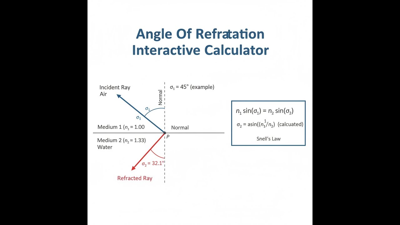
Refraction Diagram

Interactive Refraction Calculator
This calculator is intended for education, concept evaluation, and preliminary design. Results are based on the equations and assumptions described on this page, but cannot account for every real-world load case, tolerance, material property, environmental condition, installation detail, safety factor, code, or regulatory requirement. Verify all inputs, assumptions, units, and results independently before selecting components or using the result in a real application. Safety-critical, structural, medical, lifting, transportation, or regulated applications must be reviewed by a qualified engineer.
Angle of Refraction Interactive Visualizer
You can vary the incident angle and both refractive indices here to see how the light path bends in real time. This lets you see exactly where total internal reflection kicks in, check critical angle, or play with polarization effects live.
REFRACTION ANGLE
19.5°
CRITICAL ANGLE
41.8°
BREWSTER ANGLE
56.3°
REFLECTION
Normal
FIRGELLI Automations — Interactive Engineering Calculators
Core Equations
To work out the angle of refraction, here’s the direct formula:
Snell's Law
n₁ sin(θ₁) = n₂ sin(θ₂)
n₁ = refractive index of the first medium (dimensionless)
n₂ = refractive index of the second medium (dimensionless)
θ₁ = angle of incidence measured from the normal (degrees or radians)
θ₂ = angle of refraction measured from the normal (degrees or radians)
Solving for Refraction Angle
θ₂ = arcsin[(n₁/n₂) sin(θ₁)]
Only works when (n₁/n₂) sin(θ₁) ≤ 1
Critical Angle
θc = arcsin(n₂/n₁)
Exists only when n₁ > n₂ (going from higher index to lower index material)
Go past this angle and you get total internal reflection—no refracted ray escapes
Brewster's Angle
θB = arctan(n₂/n₁)
At this angle, reflected light is fully polarized
It’s where the reflected and refracted rays are at 90° to each other
Simple Example
Imagine light traveling from air (n₁ = 1.0) into glass (n₂ = 1.5) at a 30° angle.
sin(θ₂) = (1.0 / 1.5) × sin(30°) = 0.6667 × 0.5 = 0.3333
θ₂ = arcsin(0.3333) = 19.47°
So, the light bends toward the normal, which is what always happens when moving into a denser material.
Theory & Practical Applications
Fundamental Physics of Refraction
When light hits the boundary between two materials, its speed changes depending on the optical density (refractive index) of each. The refractive index n is just the ratio of the speed of light in vacuum to its speed in the material (n = c/v). In the real world, you usually can’t ignore the fact that n isn’t the same for all wavelengths, that the interface may not be perfect, or that polarization and other effects creep in, especially with lasers and coatings.
Snell’s Law is a result of what the physics says must happen at the boundary—fields must “fit” at the surface, so the combination n·sinθ has to match on both sides. If your incident light isn’t straight on, the beam bends: toward the normal in higher-index (denser) material, away from the normal in lower-index material.
Critical Angle and Total Internal Reflection
Let’s say you’re moving light from something dense (higher n) to something less dense (lower n). There’s a certain angle called the critical angle: if you go shallower than this, some energy escapes; if you go past it, all the light stays in the first medium and reflects back. That’s total internal reflection—used everywhere in fiber optics and prism instruments. Real telecoms fiber uses silica core (n ≈ 1.458) and slightly less for cladding (n ≈ 1.455), so the critical angle is about 83.5°. This means the light bounces its way down the fiber as long as it’s not too steep to the interface.
Near this angle, things get fussy: a tiny shift (for example, 0.5°) can change how much gets through, from some transmission to none at all. The transmission drops off sharply and the reflected fraction approaches 1. For total internal reflection, there’s also an evanescent wave — it doesn’t travel away, but it does go a wavelength or so into the second medium. That’s put to use in sensors and near-field microscopes.
Dispersion and Wavelength Dependence
No material has the same refractive index for all wavelengths. For example, regular glass (say, crown glass at 20°C) has n = 1.532 at 400 nm and n = 1.514 at 700 nm. That means violet bends more than red — this is why you get rainbows through prisms. Optical engineers use the Abbe number to describe how much the index changes with wavelength. If the Abbe number is low, the material has high dispersion and you have to work harder (use achromats) to stop chromatic blur. In fiber telecoms, chromatic dispersion can limit data rates: standard fiber broadens a 1 nm pulse by about 17 ps/km. To minimize this, you might use specialty fiber or separate fiber compensators with opposite sign dispersion.
Brewster's Angle and Polarization
Brewster’s angle is where reflected light off a surface is completely polarized—useful for lasers and sunglasses. At this angle, the reflected and refracted beams are at 90° to each other, and light polarized in the plane of incidence (p-polarized) isn’t reflected at all. In gas laser tubes, you’ll sometimes see windows set at Brewster’s angle to reduce loss: p-polarized light comes out clean, s-polarized gets largely reflected away. This can cut p-polarized reflection loss to about 0.01%, versus 4% at normal incidence.
In practice, this is leveraged both for efficiency and for polarization selection. Photographers use this by turning polarizing filters: unwanted polarized glare reflections from water or roads vanish at Brewster’s angle. The effect isn’t strongly wavelength-dependent, so it works across the visible range and into the IR if needed.
Industrial Applications
Anyone building underwater or air-water interface optics has to deal with refraction effects on geometry and distortion. Water makes things look closer than they are — for water, the actual depth is about 33% more than what you see, due to n ≈ 1.333. Camera domes on underwater housings help by keeping the refraction angle more consistent edge-to-edge, avoiding the distortion flat ports would cause. In industry, refractometers use this effect at the critical angle to measure refractive index with high resolution, down to about five decimal places. It’s a reliable way to check glass, measure fluid purity in pharma, or monitor petroleum products with small compositional changes.
For surveying and astronomy, atmospheric refraction matters because air isn’t evenly dense. Light curves slightly as it passes through the changing index with altitude, making objects near the horizon appear higher than they are. Surveyors working across distances longer than a kilometer must correct for this, or you’ll get millimeter-scale errors. Rangefinder systems for military or industrial work also must adjust for atmospheric model predictions in their calculations.
Worked Example: Optical Fiber Design
Problem: Design an optical fiber for 1550 nm telecom, single-mode, with reliable total internal reflection. Data: 9.2 μm core diameter, n_core = 1.4682, n_cladding = 1.4628. Find: (a) critical angle, (b) numerical aperture, (c) maximum acceptance angle (from air), (d) single-mode check by calculating V-number.
Solution:
(a) Critical Angle: First, find the boundary angle where TIR kicks in.
θc = arcsin(ncladding/ncore) = arcsin(1.4628/1.4682) = arcsin(0.9963) = 85.17°
This means guided light propagates at shallow angles relative to the core-cladding interface — just 4.83° from running straight down the fiber. That’s typical for low-dispersion, single-mode fiber.
(b) Numerical Aperture: NA tells you how much light the fiber can accept:
NA = √(n²core - n²cladding) = √(1.4682² - 1.4628²) = √(2.1556 - 2.1398) = √0.0158 = 0.1257
Here, NA is low (0.13). That limits how much light gets in, but reduces dispersion — single-mode designs always have small NA. Higher NA fibers (say, 0.3–0.5) are for much shorter runs, trading bandwidth for easier coupling.
(c) Maximum Acceptance Angle: The biggest angle from air is set by NA:
nair sin(θmax) = NA
θmax = arcsin(NA/nair) = arcsin(0.1257/1.0003) = arcsin(0.1257) = 7.22°
Anything outside this full acceptance cone (14.44° across) won’t couple well. That’s why instead of just shining a laser onto the fiber, you need careful alignment and optics. Mess up on angle by 1° and your coupling drops roughly in half.
(d) V-Number (Normalized Frequency): For single-mode, V must be below 2.405:
V = (2πa/λ) × NA = (2π × 4.6 μm / 1.55 μm) × 0.1257 = 18.66 × 0.1257 = 2.346
Here, a is core radius = 4.6 μm. With V = 2.346 just under the cutoff, you’re single-mode at 1550 nm. Get much under 1.8 and coupling gets unreasonably sensitive. Go above 2.405, and higher modes appear — which kills signal quality with modal dispersion.
This example shows that a minuscule difference in refractive indices (0.37%) lets us route huge data rates across continents by optical fiber. The small NA enables clean signal transmission — but the price is precise alignment and tight quality control at manufacturing scale.
Frequently Asked Questions
▼ Why does light bend when passing between different materials?
▼ What happens when the calculated sine value exceeds 1.0 in Snell's Law?
▼ Does refraction depend on light wavelength or color?
▼ How accurate do refractive index measurements need to be for practical applications?
▼ Why does Brewster's angle matter for laser systems and photography?
▼ How does atmospheric refraction affect precision measurements and astronomy?
Free Engineering Calculators
Explore our complete library of free engineering and physics calculators.
Browse All Calculators →🔗 Explore More Free Engineering Calculators
About the Author
Robbie Dickson — Chief Engineer & Founder, FIRGELLI Automations
Robbie Dickson brings over two decades of engineering expertise to FIRGELLI Automations. With a distinguished career at Rolls-Royce, BMW, and Ford, he has deep expertise in mechanical systems, actuator technology, and precision engineering.
Video Walkthrough - How to Use This Calculator
Need to implement these calculations?
Explore the precision-engineered motion control solutions used by top engineers.


