Designing retaining structures against lateral soil loads means getting passive earth pressure right — underestimate it and you risk structural failure; overestimate it and you waste material or create a false sense of safety. Use this Passive Earth Pressure Rankine Calculator to calculate the passive pressure coefficient (Kp), total passive force, pressure distribution, and resultant location using soil friction angle, unit weight, wall height, and surcharge inputs. It's essential for bridge abutment design, basement wall analysis, and excavation support systems. This page includes the full Rankine formula, a worked numerical example, theory on mobilization and stress states, and an FAQ covering groundwater effects, cohesion treatment, and factors of safety.
What is Passive Earth Pressure?
Passive earth pressure is the lateral resistance soil pushes back with when a structure moves into it — the opposite of active pressure, which is the force soil exerts when it moves away from a wall. It's always higher than active pressure for the same soil, and it governs how much resistance a buried or embedded structure can count on.
Simple Explanation
Think of passive earth pressure like compressing a spring — the harder you push a wall into the soil, the more the soil pushes back. Active pressure is what the soil does when it's left alone to push against a wall; passive pressure is what the soil does when the wall pushes back into it. The key practical point: passive resistance is much larger than active pressure, but it only kicks in after the wall has moved a meaningful distance into the soil.
📐 Browse all 1000+ Interactive Calculators
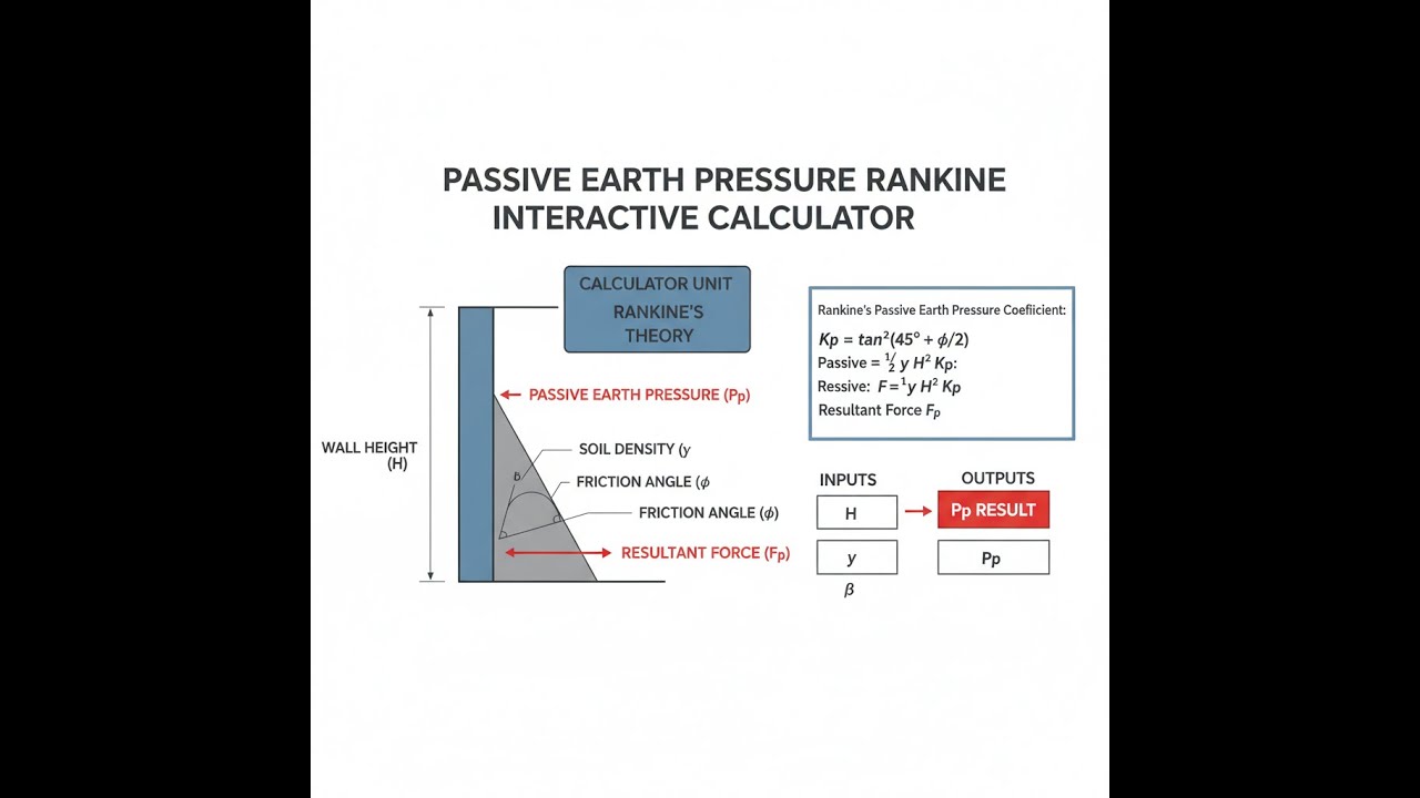
Diagram

Passive Earth Pressure Rankine Calculator
How to Use This Calculator
- Select your calculation mode from the dropdown — choose from Kp coefficient, total passive force, pressure at depth, required friction angle, resultant location, or surcharge loading.
- Enter the soil friction angle (φ) in degrees, along with any other inputs shown for your selected mode — such as unit weight, wall height, cohesion, depth, or surcharge.
- Adjust wall inclination (β) and backfill slope (α) if your geometry is not a standard vertical wall with horizontal backfill.
- Click Calculate to see your result.
Passive Earth Pressure Rankine Interactive Visualizer
Watch how soil friction angle and wall height affect passive earth pressure distribution and total resistance force. Adjust parameters to see the dramatic effect of friction angle on the passive pressure coefficient Kp and resulting force magnitude.
Kp COEFFICIENT
3.00
TOTAL FORCE
675 kN/m
MAX PRESSURE
270 kPa
FIRGELLI Automations — Interactive Engineering Calculators
Equations
Use the formula below to calculate the passive earth pressure coefficient for a vertical wall with horizontal backfill.
Basic Rankine Passive Pressure Coefficient (Vertical Wall, Horizontal Backfill)
Kp = tan²(45° + φ/2) = (1 + sin φ) / (1 - sin φ)
Where:
- Kp = Passive earth pressure coefficient (dimensionless)
- — = Internal friction angle of soil (degrees or radians)
Use the formula below to calculate passive earth pressure at any depth, including the effect of cohesion.
Passive Earth Pressure at Depth
σp = Kp × γ × z + 2c√Kp
Where:
- σp = Passive earth pressure at depth z (kPa or psf)
- γ = Unit weight of soil (kN/m³ or pcf)
- z = Depth below ground surface (m or ft)
- c = Cohesion of soil (kPa or psf)
Use the formula below to calculate total passive force per unit width of wall.
Total Passive Force per Unit Width
Pp = ½KpγH² + 2c√Kp × H
Where:
- Pp = Total passive force per unit width (kN/m or lbs/ft)
- H = Height of retaining wall (m or ft)
Note: For cohesionless soils (c = 0), the second term vanishes and the force is purely from soil overburden.
Use the formula below to calculate the passive pressure coefficient for inclined walls or sloped backfill.
General Rankine Coefficient (Inclined Wall and Backfill)
Kp = [cos α (cos β + √(cos² β - cos² α)) / (cos α (cos β - √(sin² φ - sin² α)))]²
Where:
- α = Backfill slope angle from horizontal (degrees or radians)
- β = Wall inclination from vertical (degrees or radians, positive = leaning toward soil)
Note: This general form reduces to the simple formula when α = 0 and β = 0.
Use the formula below to calculate the resultant force location for a triangular pressure distribution.
Resultant Force Location
z̄ = H/3
Where:
- z̄ = Distance from base of wall to resultant force (m or ft)
Note: For triangular pressure distribution (cohesionless soil), the resultant acts at one-third height from the base.
Use the formula below to calculate total passive force when a uniform surcharge acts on the backfill surface.
Passive Pressure with Uniform Surcharge
Pp,total = ½KpγH² + KpqH
Where:
- q = Uniform surcharge load on backfill surface (kPa or psf)
Simple Example
Given: φ = 30°, γ = 18 kN/m³, wall height H = 5 m, no cohesion (c = 0), vertical wall, horizontal backfill.
Kp = (1 + sin 30°) / (1 - sin 30°) = (1 + 0.5) / (1 - 0.5) = 1.5 / 0.5 = 3.0
Total passive force: Pp = 0.5 × 3.0 × 18 × 5² = 675 kN/m
Resultant acts at H/3 = 5/3 = 1.67 m above the base of the wall.
Theory & Engineering Applications
Rankine's passive earth pressure theory, developed by William John Macquorn Rankine in 1857, provides a fundamental framework for calculating lateral earth pressures when soil is compressed against a rigid structure. Unlike active pressure where soil tends to move away from the wall, passive pressure develops when a structure pushes into the soil mass, mobilizing significantly higher resistance forces. This condition is critical in foundation design, bridge abutments, excavation bracing, and any scenario where lateral soil resistance provides structural support.
Fundamental Theory and Stress State
Rankine's theory is based on the assumption of a semi-infinite soil mass at limiting equilibrium, where every point in the soil has reached the Mohr-Coulomb failure criterion. In the passive state, horizontal stress exceeds vertical stress, and the soil is on the verge of failure by compression rather than extension. The passive pressure coefficient Kp relates horizontal stress to vertical stress: σh = Kp × σv. For a simple vertical wall with horizontal backfill, Kp = tan²(45° + φ/2), which always exceeds unity and increases dramatically with friction angle. For example, a soil with φ = 30° yields Kp = 3.0, while φ = 35° gives Kp = 3.69°—a 23% increase for just 5 degrees of additional friction.
The critical distinction between Rankine and Coulomb theories lies in the assumed failure surface. Rankine assumes a planar failure surface at an angle of 45° - φ/2 from horizontal, while Coulomb accounts for wall friction and non-planar failure surfaces. Rankine's theory is more conservative for passive pressure (predicts lower resistance) because it neglects beneficial wall friction effects. In practice, actual passive pressures often exceed Rankine predictions by 10-30% due to wall-soil interface friction, but engineers commonly use Rankine values to maintain a safety margin since passive resistance is typically relied upon for structural stability.
The Role of Cohesion and Effective Stress
While cohesionless soils (c = 0) are most commonly analyzed, cohesive soils introduce an additional resistance term: 2c√Kp. This cohesion component provides a uniform pressure increase across the entire wall height, distinct from the triangular distribution caused by soil weight. However, practicing engineers often neglect cohesion in passive pressure calculations for three reasons: cohesion can degrade over time due to moisture changes or cyclic loading; cohesion is difficult to measure reliably; and ignoring cohesion provides a conservative design. A critical but often overlooked limitation is that cohesion-based passive pressure can theoretically extend above ground level (creating a "tension zone"), but soil cannot sustain tension, so this theoretical region must be discounted in calculations.
Effective stress principles are paramount when dealing with saturated or partially saturated soils. The friction angle φ in Rankine equations must be the effective friction angle φ', and the unit weight should reflect buoyant conditions below the water table (γ' = γsat - γwater, typically reducing from 20 kN/m³ to 10 kN/m³). Water pressure acts independently and must be added to the passive earth pressure; failure to account for this properly is a common source of retaining wall distress. For example, a 6-meter deep basement wall with saturated backfill experiences approximately 180 kPa of passive earth pressure at the base, but an additional 60 kPa of hydrostatic pressure—doubling the total lateral force if drainage is neglected.
Mobilization and Displacement Requirements
A critical practical limitation rarely emphasized in textbooks is that full passive pressure requires substantial wall movement toward the soil—typically 5-10% of wall height for dense sands and 10-20% for loose sands or clays. For a 5-meter wall, this means 25-100 cm of movement before maximum passive resistance develops. This is orders of magnitude greater than the 0.1-0.2% displacement needed to mobilize active pressure. Consequently, passive pressure should never be relied upon to prevent initial movement; it provides resistance after deformation has begun. In bridge abutment design, this displacement incompatibility means that the abutment will move before full passive resistance engages, potentially affecting bridge deck alignment.
The mobilization curve is non-linear: approximately 50% of passive resistance develops at 1-2% strain, with the remaining resistance requiring progressively larger displacements. For structures with strict serviceability limits, engineers may apply reduction factors of 0.5-0.7 to calculated passive pressures to ensure deformations remain acceptable. This reduced passive pressure can then be treated as mobilizing with minimal displacement, though this approach is conservative and increases foundation costs.
Applications in Bridge Abutment Design
Bridge abutments are classic applications where passive pressure provides critical lateral resistance against vehicle braking forces and seismic loads. Consider a 12-meter tall bridge abutment with 8 meters embedded below grade, retaining granular backfill with φ = 34° and γ = 19.5 kN/m³. The embedded portion develops Kp = 3.54, producing a total passive force of Pp = 0.5 × 3.54 × 19.5 × 8² = 2,204 kN per meter of wall length. This force acts at H/3 = 2.67 m above the base, creating a stabilizing moment of 5,881 kN·m per meter about the toe.
To evaluate stability against a 500 kN seismic force acting at the top of the abutment (generating a 6,000 kN·m overturning moment), the passive resistance alone provides a factor of safety of approximately 0.98—inadequate without considering the weight of the structure itself and additional resistance from the abutment base. However, if the abutment moves even 8 cm (1% of height), only about 50% of theoretical passive resistance mobilizes, reducing the stabilizing moment to 2,941 kN·m and creating a precarious stability condition. This example demonstrates why abutments also rely on base friction, structural weight, and battered faces rather than passive pressure alone.
Excavation Support and Braced Cuts
In urban excavations, passive pressure develops on the excavation side of struts and wales, providing critical resistance against active pressure from the retained side. A typical 10-meter deep braced excavation in medium-dense sand (φ = 32°, γ = 18.5 kN/m³) develops active pressure with Ka = 0.31, generating 288 kN/m of lateral force at the bottom. If the excavation level is lowered in stages, passive pressure on the excavation side (where previously excavated soil is recompacted or concrete is cast against the wall) provides resistance with Kp = 3.25. A 2-meter height of passive zone generates approximately 240 kN/m of resisting force—nearly matching the active thrust from 10 meters of retained soil.
The practical challenge is ensuring that the passive zone soil is properly compacted and confined. If excavation equipment disturbs the passive zone or if the soil is loose, actual resistance may be only 30-50% of theoretical passive pressure. Specifications typically require proof rolling or density testing in passive zones, and conservative designs assume Kp,design = 1.5 to 2.0 rather than theoretical values of 3.0-4.0. Additionally, if the excavation is dewatered and the passive zone remains saturated, the effective stress reduction dramatically diminishes passive resistance—a scenario that has led to several notable excavation collapses.
Fully Worked Numerical Example: Retaining Wall Stability Analysis
Consider a cantilever retaining wall with the following characteristics: wall height H = 6.5 m, embedment depth D = 1.8 m, retained granular backfill with φ = 31° and γ = 18.8 kN/m³, excavation side soil with φ = 33° and γ = 19.2 kN/m³, and cohesion c = 0 for both sides. The wall weighs 145 kN per meter including the base and stem, with the center of gravity 1.9 m from the toe. A 15 kPa uniform surcharge from adjacent pavement exists on the retained side.
Step 1: Calculate Active Pressure Coefficient (Retained Side)
φ = 31° → φrad = 0.541 radians
Ka = (1 - sin 31°) / (1 + sin 31°) = (1 - 0.515) / (1 + 0.515) = 0.485 / 1.515 = 0.320
Step 2: Calculate Active Pressure Distribution
At surface (z = 0): σa = Ka × q = 0.320 × 15 = 4.8 kPa
At base of wall (z = 6.5 m): σa = Ka(γz + q) = 0.320 × (18.8 × 6.5 + 15) = 0.320 × 137.2 = 43.9 kPa
Step 3: Calculate Total Active Force and Location
Force from surcharge: Pa,surcharge = 4.8 × 6.5 = 31.2 kN/m (acts at midheight = 3.25 m from base)
Force from soil weight: Pa,soil = 0.5 × (43.9 - 4.8) × 6.5 = 0.5 × 39.1 × 6.5 = 127.1 kN/m (acts at H/3 = 2.17 m from base)
Total active force: Pa,total = 31.2 + 127.1 = 158.3 kN/m
Step 4: Calculate Overturning Moment About Toe
Moverturning = (31.2 × 3.25) + (127.1 × 2.17) = 101.4 + 275.8 = 377.2 kN·m per meter
Step 5: Calculate Passive Pressure Coefficient (Excavation Side)
φ = 33° → Kp = (1 + sin 33°) / (1 - sin 33°) = (1 + 0.545) / (1 - 0.545) = 1.545 / 0.455 = 3.40
Step 6: Calculate Passive Pressure and Force
At embedment depth D = 1.8 m: σp = Kp × γ × D = 3.40 × 19.2 × 1.8 = 117.4 kPa
Total passive force: Pp = 0.5 × 3.40 × 19.2 × 1.8² = 0.5 × 3.40 × 62.21 = 105.8 kN/m
Acts at D/3 = 0.6 m above base of embedment = 0.6 m from ground level on excavation side
Step 7: Calculate Resisting Moment
Assuming toe is at the front edge, base extends approximately 4.2 m behind wall face:
Mwall weight = 145 × 1.9 = 275.5 kN·m per meter
Mpassive = 105.8 × 0.6 = 63.5 kN·m per meter (conservative; actual moment arm depends on wall geometry)
Mresisting,total = 275.5 + 63.5 = 339.0 kN·m per meter
Step 8: Evaluate Overturning Stability
Factor of Safety against overturning = Mresisting / Moverturning = 339.0 / 377.2 = 0.90
This is below the minimum acceptable value of 1.5-2.0 for permanent structures, indicating the wall design requires revision—either increased embedment, larger base width, or reduced retained height. If passive pressure is reduced by a factor of 2 for mobilization concerns (design Pp = 52.9 kN/m), the FOS drops to 0.81, clearly unacceptable.
This example illustrates that passive pressure, while substantial, is often insufficient alone to ensure stability. It also shows why engineers must verify multiple failure modes—this wall might also fail by sliding or bearing capacity even if overturning were addressed. The 33.5% difference between theoretical and design passive pressure (after applying reduction factors) represents the engineering judgment required to account for displacement compatibility and mobilization uncertainty.
Limitations and When Rankine Theory Fails
Rankine theory assumes a smooth, frictionless wall, which underestimates passive resistance in reality but provides a safe lower bound. It also assumes homogeneous, isotropic soil extending to infinity—conditions rarely met in practice. Layered soils, rock outcrops at shallow depth, and sloping ground surfaces all violate Rankine assumptions and require numerical methods or modified analytical approaches. Perhaps most critically, Rankine theory assumes drained conditions; in saturated clays under rapid loading, undrained shear strength governs with φ = 0 and pure cohesive behavior (different equations apply).
The theory also breaks down when wall movements are constrained. If an adjacent building prevents the wall from moving enough to mobilize passive pressure, the calculated resistance is fictitious. Similarly, if cyclic loading (such as traffic or seismic shaking) occurs, the soil may not remain at limiting equilibrium, and passive resistance may degrade—particularly in loose sands susceptible to liquefaction or sensitive clays prone to strength loss. In these cases, advanced constitutive models and dynamic analysis replace simple Rankine calculations, making the calculator a preliminary design tool rather than a final answer. For more related geotechnical calculations, explore the full engineering calculator library.
Practical Applications
Scenario: Bridge Abutment Seismic Design
Carlos, a structural engineer for the state transportation department, is evaluating whether existing bridge abutments on Interstate 90 can withstand updated seismic design requirements following new AASHTO guidelines. The abutments are 9.2 meters tall with 2.1 meters of embedment, and the site investigation revealed dense silty sand with φ = 32° and γ = 19.1 kN/m³ on the excavation side. Using the Passive Earth Pressure Rankine Calculator, Carlos calculates Kp = 3.25 and determines the embedded portion provides 222 kN/m of passive resistance. Combined with the abutment's self-weight and base friction, he confirms the structure achieves a 1.8 factor of safety against sliding under the design earthquake—just meeting the 1.5 minimum requirement. However, Carlos notes that mobilizing this passive force requires approximately 10 cm of displacement, so he recommends installing displacement transducers during the next inspection cycle to verify the abutment hasn't already moved excessively under previous seismic events. His analysis saves the state from unnecessary abutment replacement while ensuring public safety through continued monitoring.
Scenario: Basement Excavation Support Design
Jennifer, a geotechnical engineer at a foundation contractor, is designing temporary support for a 7.8-meter deep basement excavation in downtown Seattle. The excavation is immediately adjacent to a historic six-story masonry building, and any movement exceeding 15 mm could cause structural damage. The native soil is medium-dense glacial till with φ = 31° and some cohesion, but Jennifer conservatively ignores cohesion and calculates active pressure using Ka = 0.32. On the excavation side, she needs passive resistance from a 1.5-meter berm of retained soil to help stabilize the soldier piles. Using the calculator, she finds that at φ = 31°, the passive coefficient Kp = 3.13, providing 110 kN/m of resistance from the berm. However, knowing that achieving this requires 8-12 cm of movement—far exceeding her 15 mm limit—Jennifer applies a reduction factor of 2.5, designing for only 44 kN/m of passive force that will mobilize within tolerable displacements. This conservative approach requires additional tiebacks to make up the resistance deficit, but it ensures the historic building remains undamaged throughout construction. The project completes with maximum measured movements of 11 mm, validating Jennifer's careful analysis.
Scenario: Waterfront Bulkhead Replacement Planning
Marcus, a coastal engineer working for a municipal port authority, is planning the replacement of a deteriorating 150-meter long steel sheet pile bulkhead along a commercial wharf. The existing structure is showing signs of excessive deflection, and Marcus needs to determine the required embedment depth for the replacement. The marine soils consist of saturated silty sand with φ' = 29° (effective stress) and γsat = 20.5 kN/m³. Below the water table, buoyant unit weight is γ' = 10.5 kN/m³. Marcus uses the calculator to evaluate passive resistance for various embedment depths, calculating Kp = 2.83 for the effective friction angle. At a trial embedment of 3.5 meters, he calculates passive force of 181 kN/m, but he must also account for hydrostatic pressure from a 4.2-meter water depth on the harbor side. The analysis reveals that increasing embedment to 4.1 meters provides adequate passive resistance with a factor of safety of 1.6 against the combined active earth pressure and wave loading. Marcus presents the design to the port commission with cost estimates showing that the additional embedment increases project cost by only 8% compared to minimum embedment, but provides substantially better long-term performance—a trade-off the commission readily accepts given the 75-year design life of the new bulkhead.
Frequently Asked Questions
▼ What is the difference between active and passive earth pressure?
▼ Why is passive pressure so much larger than active pressure for the same soil?
▼ How much wall movement is needed to fully mobilize passive earth pressure?
▼ Should I include cohesion when calculating passive earth pressure?
▼ How does groundwater affect passive earth pressure calculations?
▼ What factor of safety should be applied to passive earth pressure?
Free Engineering Calculators
Explore our complete library of free engineering and physics calculators.
Browse All Calculators →🔗 Explore More Free Engineering Calculators
About the Author
Robbie Dickson — Chief Engineer & Founder, FIRGELLI Automations
Robbie Dickson brings over two decades of engineering expertise to FIRGELLI Automations. With a distinguished career at Rolls-Royce, BMW, and Ford, he has deep expertise in mechanical systems, actuator technology, and precision engineering.
Need to implement these calculations?
Explore the precision-engineered motion control solutions used by top engineers.


