On any slope project, the practical question is whether the slope will stay put or slide. That boils down to a factor called the "factor of safety"—a simple ratio that tells you how close you are to failure. This calculator will give you the factor of safety for a slope, using basic soil parameters: cohesion, friction angle, unit weight, slope angle, and how deep the failure surface is likely to be. This number matters anywhere slopes are cut or filled—highways, dams, mines, or residential hillsides—because when a slope fails, the cost is real and sometimes severe. Here you’ll find the formula, a step-by-step example, explanations for groundwater and earthquake considerations, and answers to common engineering questions.
What is a Slope Stability Safety Factor?
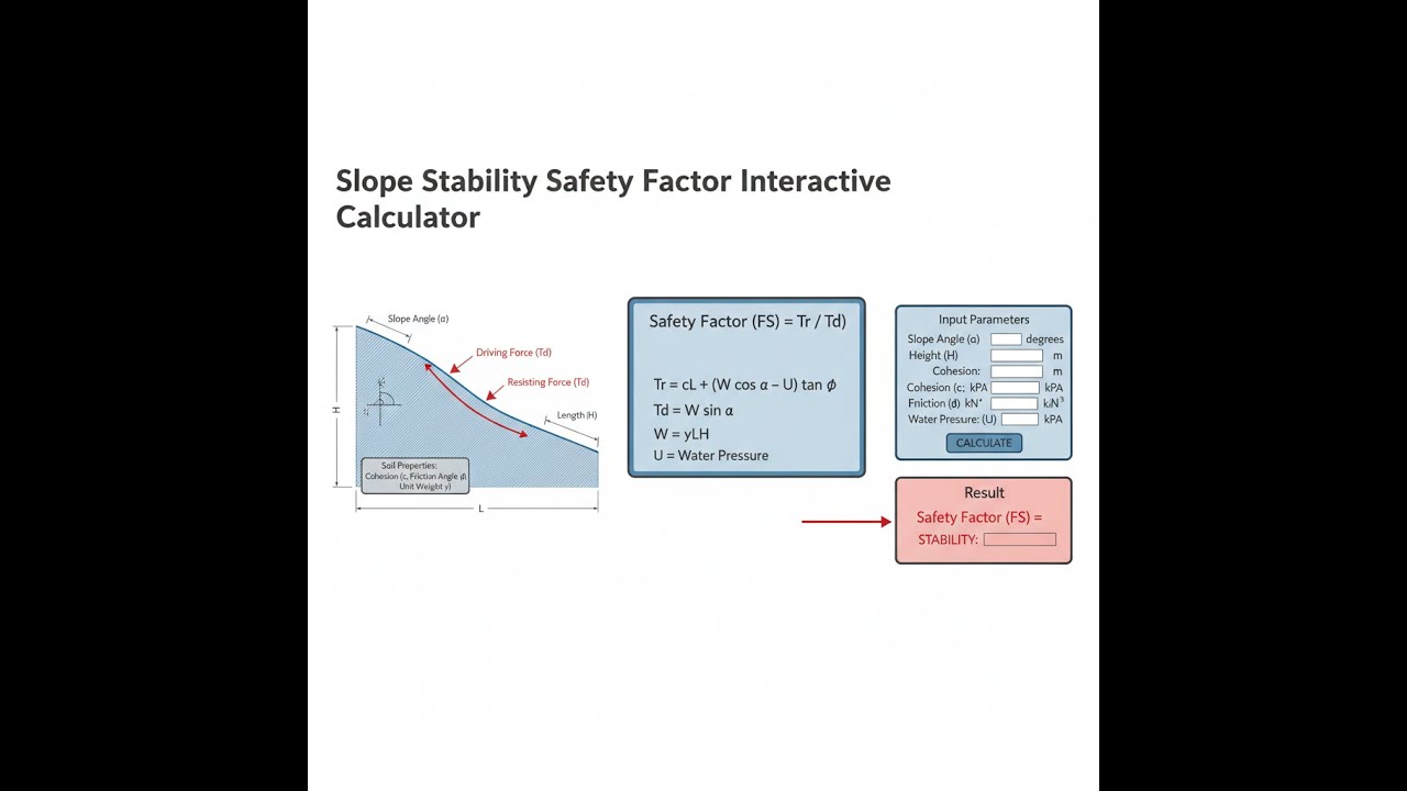
The slope stability safety factor (FS) is a ratio that compares how much resistance a slope has against sliding to how hard gravity is pushing it to slide. An FS above 1.0 means the slope is holding; below 1.0 means it has already failed or is on the verge.
Simple Explanation
Think of a slope like a box sitting on a tilted surface — gravity pulls it downhill, and friction keeps it in place. The safety factor tells you how much friction you have compared to how hard gravity is pulling. If your friction is twice the gravitational pull, your FS is 2.0 — plenty of margin. If they're equal, your FS is 1.0 — the slope is right on the edge of sliding.
📐 Browse all 1000+ Interactive Calculators
Slope Stability Diagram

How to Use This Calculator
- Select your calculation mode from the dropdown — choose from infinite slope, circular failure, groundwater, reinforced slope, or one of the back-calculation modes.
- Enter your soil parameters: cohesion (kPa), friction angle (degrees), unit weight (kN/m³), slope angle (degrees), and failure depth (m) as applicable to your selected mode.
- If using the groundwater or reinforced slope modes, enter the additional required inputs — water table depth or reinforcement force.
- Click Calculate to see your result.
Simple Example
Infinite slope mode, dry conditions:
- Cohesion c = 10 kPa, Friction angle φ = 30°
- Unit weight γ = 18 kN/m³, Slope angle β = 25°, Failure depth z = 3 m
- Driving stress = 18 × 3 × sin(25°) × cos(25°) ≈ 20.6 kPa
- Resisting stress = 10 + (18 × 3 × cos²(25°) × tan(30°)) ≈ 37.7 kPa
- FS ≈ 1.83 — Highly Stable
Slope Stability Safety Factor Calculator
Slope Stability Safety Factor Interactive Visualizer
Watch how soil cohesion, friction angle, and slope geometry directly impact the balance between driving and resisting forces. Visualize the critical failure plane and see exactly when slopes transition from stable to unstable conditions.
SAFETY FACTOR
1.83
DRIVING FORCE
20.6 kPa
RESISTING FORCE
37.7 kPa
FIRGELLI Automations — Interactive Engineering Calculators
This calculator is intended for education, concept evaluation, and preliminary design. Results are based on the equations and assumptions described on this page, but cannot account for every real-world load case, tolerance, material property, environmental condition, installation detail, safety factor, code, or regulatory requirement. Verify all inputs, assumptions, units, and results independently before selecting components or using the result in a real application. Safety-critical, structural, medical, lifting, transportation, or regulated applications must be reviewed by a qualified engineer.
Engineering Equations
Use the formula below to calculate the infinite slope factor of safety.
Infinite Slope Factor of Safety
FS = [c + γz cos2β tan φ] / [γz sin β cos β]
Where:
FS = Factor of Safety (dimensionless)
c = Cohesion of soil (kPa or psf)
γ = Unit weight of soil (kN/m³ or pcf)
z = Depth to failure plane (m or ft)
β = Slope angle from horizontal (degrees or radians)
φ = Internal friction angle of soil (degrees or radians)
Use the formula below to calculate the circular failure surface factor of safety.
Circular Failure Surface (Simplified)
FS = c / [Ns · γH]
Where:
Ns = Stability number (function of slope angle and friction angle)
H = Height of slope (m or ft)
For slopes with friction: Ns ≈ 0.181 sin β / (1 + tan φ)
Use the formula below to calculate the factor of safety for an infinite slope with a groundwater table present.
Infinite Slope with Groundwater (Effective Stress)
FS = [c + (γsat - γw)z cos2β tan φ] / [γsat z sin β cos β]
Where:
γsat = Saturated unit weight (kN/m³)
γw = Unit weight of water (9.81 kN/m³ or 62.4 pcf)
Effective stress principle reduces normal stress and thus frictional resistance
Use the formula below to calculate the critical slope angle at which FS = 1.0.
Critical Slope Angle (FS = 1.0)
sin βcrit = 2c / (γz) + tan φ
Where:
βcrit = Critical slope angle at incipient failure
Slopes steeper than βcrit will have FS less than 1.0 and are unstable
Use the formula below to calculate the factor of safety for a reinforced slope.
Reinforced Slope Factor of Safety
FS = [c + γz cos2β tan φ + (T cos β)/z] / [γz sin β cos β]
Where:
T = Tensile force in reinforcement per unit width (kN/m or lb/ft)
Reinforcement adds normal force component that increases frictional resistance
Theory & Engineering Applications
Slope stability analysis represents one of the most critical assessments in geotechnical engineering, where the factor of safety quantifies the margin between equilibrium and catastrophic failure. The factor of safety compares the total resisting forces (shear strength of soil along the potential failure surface) to the total driving forces (weight component inducing downslope movement). Values below 1.0 indicate imminent failure, while most design codes require FS ≥ 1.3 for temporary slopes and FS ≥ 1.5 for permanent structures to account for uncertainties in soil parameters, construction variability, and extreme loading conditions such as earthquakes or rapid drawdown.
Infinite Slope Analysis: Planar Failure Mechanics
The infinite slope model assumes a failure surface parallel to the ground surface at depth z, applicable when slope length significantly exceeds failure depth and soil properties remain uniform. This analytical approach provides closed-form solutions ideal for preliminary design of highway embankments, natural hillslopes in residual soils, and tailing dam facilities. The driving stress equals γz sin β cos β, representing the weight component parallel to the failure plane, while resisting stress combines cohesive strength c and frictional resistance from effective normal stress. A non-obvious limitation emerges when the slope angle β approaches the friction angle φ—in purely frictional soils (c = 0), the factor of safety reduces to tan φ / tan β, meaning slopes steeper than φ will always fail regardless of depth.
The mathematical decomposition reveals that normal stress on the failure plane equals γz cos²β, accounting for both the soil column weight and the geometric projection onto the inclined surface. This quadratic dependence on cosine creates the counterintuitive result that very shallow slopes (β approaching 0°) develop minimal shear stress but also minimal normal stress, producing indeterminate behavior as both numerator and denominator trend toward zero. Engineers must recognize that infinite slope analysis becomes invalid for β less than approximately 10° due to three-dimensional edge effects and for slopes where the failure surface intersects the toe, requiring circular or composite failure analysis instead.
Circular Failure Analysis: Rotational Slide Mechanics
When slopes exceed certain height-to-base ratios or consist of homogeneous clay with low friction angles, failure typically occurs along curved surfaces approximated by circular arcs. The simplified stability number approach expresses the factor of safety as c/(NsγH), where the stability number Ns depends on slope geometry and soil friction through charts developed by Taylor (1937) or the simplified expression Ns ≈ 0.181 sin β / (1 + tan φ). This method becomes particularly valuable for rapid assessment of cut slopes in cohesive soils, though more rigorous approaches like Spencer's method or Morgenstern-Price should be employed for final design of critical structures.
The moment equilibrium for circular failure requires calculating the driving moment (soil weight times moment arm about the rotation center) and resisting moment (cohesive and frictional forces integrated along the arc length). For purely cohesive soils (φ = 0), the critical circle depth reaches approximately 1.3H for 2:1 slopes, while increasing friction angles shift the critical circle to progressively shallower surfaces, eventually transitioning to toe circles for φ above 20°. Design engineers often evaluate multiple circle centers and radii to identify the minimum factor of safety, with modern slope stability software automating this search through optimization algorithms that test thousands of potential failure surfaces.
Groundwater Effects: Effective Stress and Pore Pressure
Groundwater represents the single most destabilizing influence in slope engineering, reducing the factor of safety through two mechanisms: (1) pore water pressure reduces effective normal stress by the magnitude of the pore pressure u, thereby decreasing frictional resistance proportional to tan φ, and (2) saturated unit weight increases driving forces compared to dry or partially saturated conditions. The effective stress equation σ' = σ - u demonstrates that a groundwater table at the failure surface (u = γwz) reduces the effective unit weight from γ to γsat - γw, typically decreasing FS by 30-50% in cohesionless soils. This explains why landslides preferentially occur during intense rainfall or rapid snowmelt when transient perched water tables develop along impermeable layers.
Steady-state seepage analysis using flow nets or finite element groundwater modeling provides the pore pressure distribution required for effective stress stability calculations. The critical piezometric condition occurs when flow lines parallel the slope, creating constant pore pressure equal to γw times the vertical distance to the water table, maximizing effective stress reduction across the entire failure surface. Engineering mitigation strategies include horizontal drains installed perpendicular to the slope at 15-25m spacing, drainage blankets of free-draining gravel, or deep vertical wells with pumping systems, all designed to lower the phreatic surface and restore effective stress. A crucial design insight: reducing the water table elevation by even 1-2m can increase FS from marginal (1.1-1.2) to acceptable (1.4-1.5) ranges.
Worked Example: Highway Cut Slope Design
A highway project requires a 35m long cut slope through residual clay with the following laboratory-tested properties: cohesion c = 18 kPa, friction angle φ = 26°, saturated unit weight γsat = 19.2 kN/m³. The design slope angle β = 24° (approximately 2.25:1 horizontal to vertical). Geotechnical investigation indicates potential failure along a plane 4.2m below the surface, parallel to the slope. Groundwater monitoring reveals a perched water table at 2.8m depth during spring conditions. Calculate the factor of safety for both dry and saturated conditions.
Step 1: Dry Condition Analysis
Using infinite slope equation for dry soil (unit weight γ = 18.5 kN/m³ for unsaturated clay):
Normal stress on failure plane: σn = γz cos²β = 18.5 × 4.2 × cos²(24°) = 18.5 × 4.2 × 0.8332 = 64.73 kPa
Shear stress: τ = γz sin β cos β = 18.5 × 4.2 × sin(24°) × cos(24°) = 18.5 × 4.2 × 0.4067 × 0.9135 = 28.92 kPa
Resisting stress: τr = c + σn tan φ = 18 + 64.73 × tan(26°) = 18 + 64.73 × 0.4877 = 18 + 31.57 = 49.57 kPa
Factor of Safety: FSdry = τr / τ = 49.57 / 28.92 = 1.714
Step 2: Saturated Condition Analysis
Water table at zw = 2.8m means entire 4.2m failure depth is saturated.
Effective normal stress: σ'n = (γsat - γw)z cos²β = (19.2 - 9.81) × 4.2 × cos²(24°) = 9.39 × 4.2 × 0.8332 = 32.87 kPa
Shear stress (total stress): τ = γsat z sin β cos β = 19.2 × 4.2 × 0.4067 × 0.9135 = 29.99 kPa
Resisting stress: τr = c + σ'n tan φ = 18 + 32.87 × 0.4877 = 18 + 16.03 = 34.03 kPa
Factor of Safety: FSsat = τr / τ = 34.03 / 29.99 = 1.135
Step 3: Engineering Assessment
The dry condition FS = 1.71 exceeds the minimum requirement of 1.5 for permanent slopes, indicating acceptable stability. However, the saturated condition FS = 1.13 falls below the 1.25 minimum threshold for temporary stability and approaches the critical failure value of 1.0. The groundwater reduces FS by 34%, a typical magnitude for cohesive-frictional soils. This analysis demonstrates that the slope requires subsurface drainage to maintain adequate safety margins during wet seasons.
Step 4: Drainage System Design
To restore FS to 1.5 under saturated conditions, we calculate the required water table lowering. Working backwards from target FS = 1.5:
Required τr = 1.5 × 29.99 = 44.99 kPa
Required effective stress: σ'req = (44.99 - 18) / tan(26°) = 26.99 / 0.4877 = 55.36 kPa
Since σ'n = (γsat - γw)zeff cos²β, the effective saturated depth becomes:
zeff = 55.36 / (9.39 × 0.8332) = 55.36 / 7.82 = 7.08m
This exceeds our actual failure depth of 4.2m, meaning we need the water table below the failure surface. Installing horizontal drains at 3m depth (0.9m above failure plane) with 20m spacing would intercept seepage and maintain dry conditions above the critical zone, restoring FS to acceptable values. Alternative solutions include flattening the slope to 3:1 (β = 18.4°), which would increase FS to 1.52 even under fully saturated conditions, though this requires additional right-of-way acquisition.
Advanced Considerations for Professional Practice
Real-world slope stability analysis extends beyond these simplified approaches to address complexities including non-circular failure surfaces (logarithmic spirals, composite wedges), three-dimensional effects at slope ends or near structures, tension crack development in the upper crest region, progressive failure where local overstressing redistributes loads, and time-dependent strength degradation in overconsolidated clays. The factor of safety concept itself has limitations—it applies a uniform reduction to all strength parameters rather than recognizing that cohesion uncertainty typically exceeds friction angle uncertainty by a factor of 2-3. Probabilistic approaches using Monte Carlo simulation to propagate soil property variability through stability calculations provide more rigorous treatment of uncertainty, expressing results as probability of failure rather than a single FS value.
Slope reinforcement systems including soil nails (grouted steel bars at 1.5-2.5m spacing), geosynthetic layers (tensile strength 50-200 kN/m), or micropiles transfer tensile forces into stable ground, effectively increasing the resisting moment or adding an upslope component to offset gravitational driving forces. The reinforcement contribution T cos β / z in the equation represents the average normal stress increase across the failure depth, though actual designs require verification of pullout capacity, facing connection, and global stability. Modern specifications require instrumentation of critical slopes with inclinometers measuring horizontal displacement at depth, piezometers monitoring pore pressure, and surface monuments tracked by survey or GPS, creating real-time monitoring systems that trigger alerts when measured behavior deviates from predicted performance. For additional geotechnical engineering resources, visit the complete calculator library.
Practical Applications
Scenario: Residential Development on Hillside Terrain
Jennifer, a civil engineer with a land development firm, is evaluating a 45-acre residential subdivision proposed for rolling terrain with natural slopes ranging from 15° to 28°. Geotechnical borings reveal silty clay with c = 22 kPa and φ = 24°, with seasonal groundwater fluctuations between 3m and 6m depth. She uses the slope stability calculator to analyze multiple slope configurations, discovering that the existing 26° slopes have FS = 1.18 during wet season conditions—below the 1.5 minimum required by local building codes. By inputting different slope angles into the calculator's infinite slope mode, Jennifer determines that regrading to 20° slopes increases FS to 1.58, making lots safe for construction. She also models the groundwater mode to demonstrate that installing French drains along the base of each slope raises FS to 1.72 even at the steeper 24° angle, providing the developer with cost-effective alternatives that satisfy both safety requirements and minimize earthwork quantities. This analysis directly informs grading plans, drainage specifications, and geotechnical recommendations in the development's engineering reports.
Scenario: Highway Widening Project Stability Assessment
Marcus, a transportation engineer for the state DOT, is designing a highway widening that requires cutting a 9m high slope through weathered shale at β = 32°. Laboratory testing yields c = 15 kPa, φ = 28°, and γ = 19.5 kN/m³, but the project geotechnical report flags potential circular failure surfaces. Using the calculator's circular failure mode, Marcus inputs these parameters and calculates FS = 1.24—marginally below the 1.3 threshold for temporary construction slopes. He switches to the required cohesion mode, setting target FS = 1.5, and discovers that soil improvement to c = 28 kPa would provide adequate safety. This prompts evaluation of two alternatives: (1) installing 6m long soil nails at 2m spacing to increase effective cohesion, or (2) flattening the slope to 2.5:1 (β = 21.8°). By recalculating with the adjusted angle, Marcus finds FS jumps to 1.64 without reinforcement, and the project team selects this option despite requiring additional right-of-way acquisition. The calculator's instant feedback accelerates the iterative design process that would otherwise require running commercial software for each configuration change, ultimately saving the agency $340,000 compared to the soil nail alternative while improving long-term maintenance costs.
Scenario: Open-Pit Mining Bench Optimization
Rajesh, a mining engineer at a copper operation, is responsible for optimizing haul road bench angles in weathered rock with c = 35 kPa and φ = 38°. Corporate safety standards require FS ≥ 2.0 for all permanent mining infrastructure, significantly more conservative than civil engineering practice due to worker exposure and equipment value. Using the infinite slope calculator with γ = 22 kN/m³ and assumed failure depth z = 5m (based on observed joint spacing), Rajesh evaluates bench angles from 30° to 45°. At β = 38°, FS = 1.87—below requirements. Rather than immediately flattening slopes and increasing overburden removal costs by an estimated $2.3 million annually, Rajesh uses the reinforced slope mode to model the effect of rock bolts providing T = 75 kN/m per bench. This yields FS = 2.15, meeting safety criteria while preserving the steeper geometry. He then conducts sensitivity analysis by varying the friction angle ±3° (representing uncertainty in lab testing of weathered rock) and confirms that even at φ = 35°, the reinforced configuration maintains FS = 1.96. This quantitative justification supports his recommendation to mine management for a controlled blasting and rock bolt installation program that maintains productivity while ensuring regulatory compliance and worker safety across the 180m deep excavation.
Frequently Asked Questions
What is the minimum acceptable factor of safety for slope design? +
How does groundwater affect slope stability calculations? +
When should I use infinite slope versus circular failure analysis? +
How do I determine appropriate soil strength parameters for stability calculations? +
What reinforcement options exist for improving marginal slope stability? +
How does seismic loading affect slope stability factor of safety? +
Free Engineering Calculators
Explore our complete library of free engineering and physics calculators.
Browse All Calculators →🔗 Explore More Free Engineering Calculators
About the Author
Robbie Dickson — Chief Engineer & Founder, FIRGELLI Automations
Robbie Dickson brings over two decades of engineering expertise to FIRGELLI Automations. With a distinguished career at Rolls-Royce, BMW, and Ford, he has deep expertise in mechanical systems, actuator technology, and precision engineering.
Video Walkthrough - How to Use This Calculator
Need to implement these calculations?
Explore the precision-engineered motion control solutions used by top engineers.


