Keeping a nuclear reactor core at safe temperatures means continuously removing hundreds or thousands of megawatts of fission heat — and getting the coolant flow wrong has catastrophic consequences. Use this Reactor Coolant Flow Calculator to calculate mass flow rate, heat removal capacity, temperature rise, pump power, coolant velocity, and Reynolds number using thermal power, specific heat, temperature rise, pressure drop, and flow geometry inputs. It's directly applicable to pressurized water reactors (PWRs), boiling water reactors (BWRs), and small modular reactor (SMR) design and safety analysis. This page includes the governing equations, a full worked PWR example, flow theory, and a practical FAQ.
What is reactor coolant flow?
Reactor coolant flow is the continuous circulation of a fluid — usually pressurized water — through a nuclear reactor core to carry away the heat produced by fission. The flow rate must be high enough to prevent the fuel from overheating under all operating conditions.
Simple Explanation
Think of the reactor core like a very powerful electric stove burner and the coolant like water flowing over it — the faster the water flows, the more heat it can carry away before it gets too hot. In a nuclear plant, massive pumps drive tens of thousands of kilograms of water per second through the core every second. Get the flow rate wrong — too low — and the fuel overheats; too high and the pumps waste enormous power and risk erosion damage.
📐 Browse all 1000+ Interactive Calculators
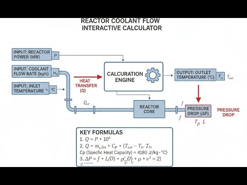
Reactor Coolant Flow System Diagram

Reactor Coolant Flow Calculator
How to Use This Calculator
- Select your calculation mode from the dropdown — mass flow rate, heat removal, temperature rise, pump power, coolant velocity, or Reynolds number.
- Enter the required inputs for your chosen mode — thermal power (MW), mass flow rate (kg/s), specific heat (kJ/kg·K), temperature rise (°C), pressure drop (kPa), pump efficiency (%), flow area (m²), density (kg/m³), velocity (m/s), hydraulic diameter (m), or dynamic viscosity (Pa·s) as prompted.
- Use the "Try Example" button to load realistic PWR values if you want to see a sample calculation first.
- Click Calculate to see your result.
Reactor Coolant Flow Interactive Visualizer
Watch how thermal power, flow rate, and temperature rise interact in real-time to maintain safe reactor core cooling. Adjust parameters to see the critical balance between heat removal capacity and coolant system requirements.
TEMP RISE
32.1°C
VELOCITY
4.3 m/s
REYNOLDS
2.4×10⁵
FIRGELLI Automations — Interactive Engineering Calculators
Governing Equations
Simple Example
A reactor produces 1000 MW thermal. The coolant has a specific heat of 5.0 kJ/kg·K and the allowed temperature rise across the core is 40°C.
ṁ = (1000 × 1000) / (5.0 × 40) = 5,000 kg/s required mass flow rate.
If coolant density is 700 kg/m³ and flow area is 2.0 m², coolant velocity = 5000 / (700 × 2.0) = 3.57 m/s.
Heat Balance Equation
Use the formula below to calculate reactor heat removal.
Q = ṁ · cp · ΔT
Where:
- Q = Thermal power removed (MW or kW)
- ṁ = Mass flow rate of coolant (kg/s)
- cp = Specific heat capacity at constant pressure (kJ/kg·K)
- ΔT = Temperature rise across reactor core (°C or K)
Mass Flow Rate Calculation
Use the formula below to calculate required coolant mass flow rate.
ṁ = Q / (cp · ΔT)
This fundamental relationship determines the required coolant circulation rate to remove a specified thermal power given the allowable temperature rise and coolant properties.
Coolant Velocity
Use the formula below to calculate coolant velocity from mass flow rate, density, and flow area.
v = ṁ / (ρ · A)
Where:
- v = Average coolant velocity (m/s)
- ρ = Coolant density (kg/m³)
- A = Flow cross-sectional area (m²)
Pump Power Requirement
Use the formula below to calculate required reactor coolant pump shaft power.
Pshaft = (Qvol · Δp) / ηpump
Where:
- Pshaft = Required shaft power (kW or MW)
- Qvol = Volumetric flow rate (m³/s) = ṁ / ρ
- Δp = System pressure drop (kPa or MPa)
- ηpump = Pump efficiency (decimal fraction)
Reynolds Number
Use the formula below to calculate Reynolds number and determine flow regime in reactor coolant channels.
Re = (ρ · v · Dh) / μ
Where:
- Re = Reynolds number (dimensionless)
- Dh = Hydraulic diameter (m)
- μ = Dynamic viscosity (Pa·s or kg/m·s)
Reynolds number determines flow regime and influences heat transfer correlations and pressure drop calculations in reactor thermal-hydraulic analysis.
Theory & Engineering Applications
Reactor coolant flow represents one of the most critical safety systems in nuclear power plant design, serving the dual purpose of removing fission heat from the reactor core and moderating neutron energy in certain reactor types. The primary coolant system operates under extreme conditions—typically 15.5 MPa pressure and temperatures ranging from 290°C inlet to 325°C outlet in pressurized water reactors (PWRs)—requiring precise thermal-hydraulic analysis to ensure adequate cooling under all operating conditions including normal operation, transient events, and design basis accidents.
Fundamental Heat Transfer Mechanisms in Reactor Cores
The heat removal process in nuclear reactors involves several coupled phenomena that distinguish it from conventional thermal systems. Fission energy deposition creates a highly non-uniform power distribution within the reactor core, with radial peaking factors typically ranging from 1.3 to 1.6 and axial peaking factors of 1.4 to 1.5. This means the hottest fuel assemblies may generate 50-60% more power than the core average, creating localized hot channels that dictate minimum required flow rates. The thermal-hydraulic designer must ensure departure from nucleate boiling ratio (DNBR) remains above safety limits—typically 1.3 or higher—throughout the core even in these peak power regions.
What makes reactor coolant flow particularly challenging is the exponential relationship between heat transfer coefficient and coolant velocity. For turbulent flow in rod bundles, the Dittus-Boelter correlation shows heat transfer coefficient proportional to velocity to the 0.8 power and inversely proportional to hydraulic diameter to the 0.2 power. This means reducing flow rate by 20% decreases heat transfer coefficient by approximately 17%, potentially triggering the transition from nucleate boiling to film boiling—a catastrophic condition where the vapor film blanket insulates the fuel cladding, causing rapid temperature excursion and potential fuel failure. This non-linear behavior creates narrow operating margins that require conservative design approaches.
Coolant Property Variations and System Design
Unlike industrial heat exchangers operating with relatively constant fluid properties, reactor primary coolant experiences significant property variations due to the temperature and pressure gradients throughout the system. Water density decreases from approximately 735 kg/m³ at the core inlet to 695 kg/m³ at the outlet at typical PWR conditions, creating buoyancy forces that enhance natural circulation but complicate flow distribution calculations. The specific heat capacity varies from 5.65 kJ/kg·K at inlet conditions to 6.15 kJ/kg·K at outlet conditions, meaning the simple heat balance equation Q = ṁ·cp·ΔT requires integration across the temperature range for accurate results rather than using average properties.
Dynamic viscosity decreases with increasing temperature, dropping from approximately 9.0×10⁻⁵ Pa·s at 290°C to 7.8×10⁻⁵ Pa·s at 325°C. This 13% reduction affects Reynolds numbers and friction factors throughout the primary loop, influencing pressure drop calculations that determine required pump head. Modern reactor designs account for these variations using property tables evaluated at local conditions rather than bulk average values, improving prediction accuracy for critical parameters like minimum DNBR location.
Primary Coolant Pump Engineering
Reactor coolant pumps represent some of the largest and most critical rotating equipment in nuclear facilities, with individual units in large PWRs delivering 6-8 MW of shaft power to circulate 20,000-25,000 kg/s of coolant through each loop. These pumps must maintain flow during all operating modes while meeting stringent seismic qualifications, leak-tightness requirements, and providing sufficient coastdown time following loss of power to prevent core damage. The pump design incorporates several unique features: controlled leakage seals to prevent radioactive coolant escape, high-inertia flywheels to extend coastdown period, and vertical shaft orientation with the motor mounted above the reactor coolant system to minimize floor space and facilitate maintenance.
Pump power calculation requires careful attention to system pressure drop, which includes elevation head, friction losses in piping and components, and form losses at flow restrictions. A typical large PWR primary loop experiences approximately 350-450 kPa total pressure drop, with roughly 120 kPa across the reactor core, 80 kPa in the steam generator, and the remainder distributed among piping, valves, and fittings. The pump must overcome this resistance while maintaining flow rate within ±2% to ensure uniform power distribution and predictable thermal-hydraulic behavior.
Pump efficiency typically ranges from 82-87%, with the remainder converted to heat that must be accounted for in the heat balance—a non-trivial contribution of 15-20 MW thermal per pump in large units.
Worked Example: PWR Primary System Design
Consider designing the primary coolant system for a 3400 MW thermal four-loop PWR with the following specifications: core inlet temperature 292.8°C, core outlet temperature 326.7°C, system pressure 15.51 MPa, and specific heat capacity averaging 5.82 kJ/kg·K at operating conditions.
Step 1: Calculate total required mass flow rate
Using the heat balance equation:
ṁ = Q / (cp · ΔT) = 3400 MW / (5.82 kJ/kg·K × (326.7 - 292.8) K)
ṁ = 3,400,000 kW / (5.82 kJ/kg·K × 33.9 K)
ṁ = 3,400,000 / 197.3 = 17,232 kg/s total
Step 2: Determine flow per loop
For a four-loop design with equal flow distribution:
ṁloop = 17,232 / 4 = 4,308 kg/s per loop
Step 3: Calculate volumetric flow rate
Using average coolant density of 715 kg/m³ at mean temperature:
Qvol = ṁloop / ρ = 4,308 kg/s / 715 kg/m³ = 6.026 m³/s per loop
Step 4: Determine coolant velocity in reactor vessel
Assuming reactor vessel downcomer flow area of 3.85 m²:
vdowncomer = Qvol / A = 6.026 m³/s / 3.85 m² = 1.565 m/s
Step 5: Calculate core flow velocity
With core flow area of 4.92 m² (accounting for fuel assembly blockage):
vcore = 6.026 m³/s / 4.92 m² = 1.225 m/s average
This represents bulk average velocity; actual velocity in hot channels will be approximately 1.35-1.40 m/s due to flow redistribution based on power peaking.
Step 6: Determine pump power requirement
Assuming total loop pressure drop of 385 kPa and pump efficiency of 85%:
Phydraulic = Qvol × Δp = 6.026 m³/s × 385 kPa = 2,320 kW
Pshaft = Phydraulic / η = 2,320 kW / 0.85 = 2,729 kW per pump
Including motor efficiency of 96%:
Pmotor = 2,729 / 0.96 = 2,843 kW electrical power required per pump
Step 7: Verify Reynolds number for turbulent flow
Using hydraulic diameter of 0.0117 m for typical fuel assembly subchannel and dynamic viscosity of 8.4×10⁻⁵ Pa·s:
Re = (ρ × v × Dh) / μ = (715 kg/m³ × 1.225 m/s × 0.0117 m) / (8.4×10⁻⁵ Pa·s)
Re = 10.25 / 8.4×10⁻⁵ = 122,024
This confirms fully developed turbulent flow (Re well above 10,000), ensuring effective convective heat transfer with Nusselt number approximately 350-400 for this geometry.
Step 8: Calculate heat addition to coolant from pump work
Inefficiency of pumping is converted to heat:
Qpump = Pshaft × (1 - η) = 2,729 kW × (1 - 0.85) = 409 kW per pump
Total for four pumps: 1,636 kW or 1.64 MW thermal added to primary system, representing 0.048% of core thermal power—negligible for heat balance but important for precise temperature distribution calculations.
Advanced Considerations in Modern Reactor Design
Small modular reactors (SMRs) and advanced reactor concepts introduce additional complexity to coolant flow analysis. Integral PWR designs eliminate large-bore primary loop piping by locating steam generators inside the reactor pressure vessel, reducing coolant inventory but creating challenges for flow distribution and pump integration. Some designs employ canned motor pumps with the motor immersed in primary coolant, eliminating shaft seals but requiring careful thermal management to prevent motor overheating. Natural circulation reactors eliminate pumps entirely during normal operation, relying on density differences between hot and cold legs to drive flow—a passive safety feature that requires larger elevation differences and larger diameter piping to achieve adequate flow rates.
For a comprehensive collection of nuclear and thermal engineering resources, visit the FIRGELLI engineering calculator library covering reactor physics, heat transfer, fluid mechanics, and structural analysis tools used in power plant design and analysis.
Practical Applications
Scenario: Refueling Outage Flow Verification
Maria, a senior reactor engineer at a three-loop PWR facility, is preparing the plant for restart following a refueling outage where one reactor coolant pump motor was replaced. Before achieving criticality, she must verify that the new pump delivers the required 23,476 kg/s mass flow rate at the design point. Using the calculator in mass flow mode, she inputs the rated thermal power of 3,565 MW, core inlet temperature of 291.4°C, outlet temperature of 325.8°C, and water specific heat of 5.78 kJ/kg·K at operating conditions. The calculator confirms the design flow rate and provides the volumetric flow equivalent of 32.8 m³/s assuming nominal density. She then uses the pump power mode to verify the replacement motor's 7,240 kW rating is adequate for the measured loop pressure drop of 394 kPa at 84.3% pump efficiency. The calculations confirm proper pump sizing, allowing her to sign off on the pre-startup checklist and proceed with reactor physics testing.
Scenario: Small Modular Reactor Core Design
Dr. James Chen, lead thermal-hydraulics engineer for a company developing a 300 MWth integral pressurized water reactor, is optimizing coolant flow distribution for the compact core design. The innovative vessel arrangement requires careful velocity management to prevent flow-induced vibration in the internal steam generators while maintaining adequate core cooling. Using the velocity calculation mode, he determines that the 2,847 kg/s total flow through the 1.83 m² core flow area produces an average velocity of 2.18 m/s at 695 kg/m³ density—higher than conventional PWRs due to the compact design but still within acceptable limits. He then switches to Reynolds number mode, inputting velocity 2.18 m/s, subchannel hydraulic diameter 0.0094 m, and viscosity 7.9×10⁻⁵ Pa·s to calculate Re = 191,300, confirming fully turbulent flow for reliable heat transfer correlations. These calculations validate that the SMR design maintains proper thermal-hydraulic characteristics despite the 50% reduction in coolant inventory compared to traditional plants, supporting the licensing case for this innovative reactor concept.
Scenario: Accident Analysis for Safety Report
Rebecca Thompson, a nuclear safety analyst preparing the Updated Final Safety Analysis Report for a plant license renewal, must demonstrate adequate core cooling during a postulated loss of one reactor coolant pump scenario. The plant operates at 3,817 MW thermal with four loops normally providing 4,544 kg/s each. Using the heat removal capacity mode, she calculates that three pumps providing 13,632 kg/s total flow with 5.71 kJ/kg·K specific heat and temperature rise limited to 37.2°C can remove 2,898 MW—sufficient to cool the reactor after automatic power reduction to 75% following the pump trip. She documents this analysis showing that even with one pump out of service, the remaining three pumps exceed the minimum required flow rate by 14.7% margin, meeting regulatory requirements for single failure tolerance. The temperature rise calculation mode confirms the increased ΔT remains within Technical Specification limits of 40°C maximum, and the core exit temperature stays below the 334°C saturation temperature with adequate subcooling margin. These calculations form the analytical basis for concluding the plant can safely accommodate the design basis event, supporting the 20-year license extension application.
Frequently Asked Questions
▼ Why do reactor coolant pumps require such high power compared to industrial pumps?
▼ How does coolant temperature rise vary with reactor power level?
▼ What determines the minimum allowable coolant flow rate in a nuclear reactor?
▼ How do different reactor types compare in coolant flow requirements?
▼ What role does Reynolds number play in reactor thermal-hydraulic safety?
▼ How is coolant flow verified and monitored during reactor operation?
Free Engineering Calculators
Explore our complete library of free engineering and physics calculators.
Browse All Calculators →🔗 Explore More Free Engineering Calculators
About the Author
Robbie Dickson — Chief Engineer & Founder, FIRGELLI Automations
Robbie Dickson brings over two decades of engineering expertise to FIRGELLI Automations. With a distinguished career at Rolls-Royce, BMW, and Ford, he has deep expertise in mechanical systems, actuator technology, and precision engineering.
Need to implement these calculations?
Explore the precision-engineered motion control solutions used by top engineers.


