When you’re designing radiation shielding, just guessing the numbers is asking for cost overruns—or worse, a real safety problem if you under-build. Use the Shielding Thickness Gamma Calculator here to work out how much material you actually need, what the resulting intensity will be, the half-value and tenth-value layers, and the attenuation coefficients. You enter the initial and desired intensity, attenuation data, and pick the shield material. This isn’t just for show: these numbers go straight into the wall thickness for hot labs, radiography bunkers, or reactor control rooms. The page lays out the key equations, a real step-by-step example, full theory (including how buildup screws with simple calcs), and includes practical engineering FAQ at the end.
What is gamma ray shielding thickness?
Gamma ray shielding thickness is simply the depth of material—usually lead, concrete, steel, or something similar—needed to cut down the intensity of gamma radiation to your target level. Thicker, denser, higher-Z materials stop more gamma rays, but nothing will block all of them completely.
Simple Explanation
Gamma radiation passing through shielding acts a lot like light hitting tinted glass—the more material there is, the less comes out the other side, and it drops off fast. But, the reduction is a percentage of what’s left, not a fixed amount per layer—that’s why the attenuation math is exponential. Add a centimeter and you’re often halving what gets through instead of just subtracting a fixed number. Double the thickness, and the fraction that gets through drops far more than by half.
📐 Browse all 1000+ Interactive Calculators
Table of Contents
How to Use This Calculator
- Select a Calculation Mode from the dropdown — choose whether you want to find required thickness, final intensity, half-value layer, tenth-value layer, attenuation coefficient, or intensity with buildup factor.
- Enter your Initial Intensity (I₀) and target Final Intensity (I) in consistent units (R/hr, mR/hr, or Sv/hr), or thickness if that mode requires it.
- Select a Shielding Material to auto-fill the linear attenuation coefficient, or choose Custom and enter your own μ value in cm⁻¹.
- Click Calculate to see your result.
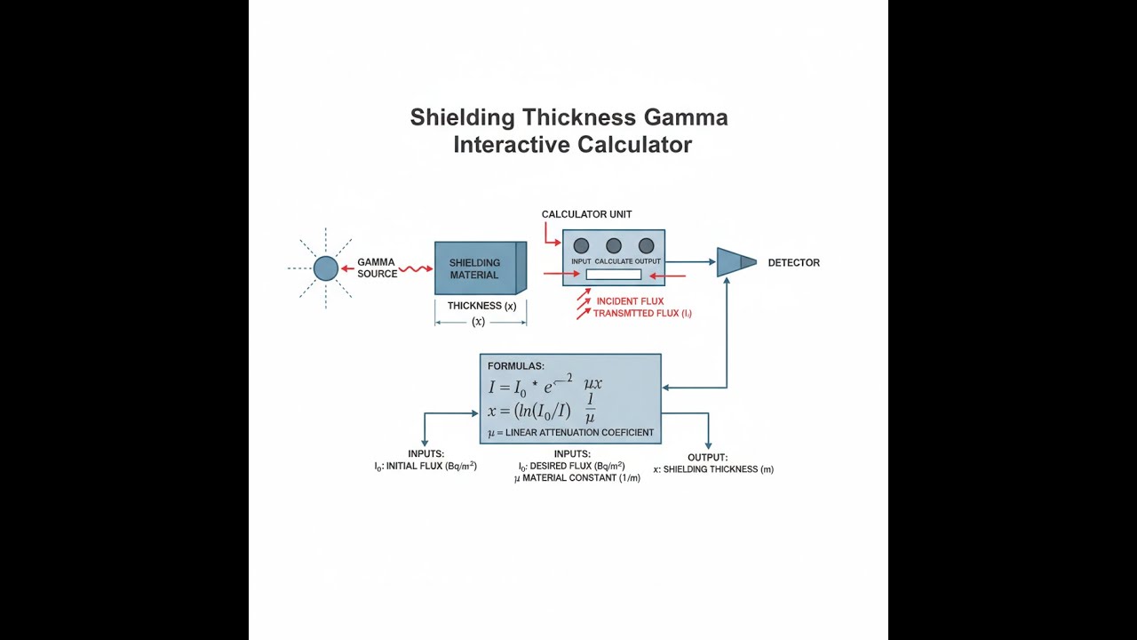
Shielding Diagram

Gamma Shielding Calculator
This calculator is intended for education, concept evaluation, and preliminary design. Results are based on the equations and assumptions described on this page, but cannot account for every real-world load case, tolerance, material property, environmental condition, installation detail, safety factor, code, or regulatory requirement. Verify all inputs, assumptions, units, and results independently before selecting components or using the result in a real application. Safety-critical, structural, medical, lifting, transportation, or regulated applications must be reviewed by a qualified engineer.
Gamma Shielding Thickness Interactive Visualizer
Here you can watch how gamma intensity actually falls off as you add more shielding. Adjust thickness, energy, and the material type to see in real time how much the dose drops. This is how you get an intuitive feel for why even a few more centimeters can make orders of magnitude difference on what leaks through the barrier.
TRANSMITTED
32 mR/hr
REDUCTION
96.8%
HALF LAYERS
5.0 HVL
TENTH LAYERS
1.5 TVL
FIRGELLI Automations — Interactive Engineering Calculators
Shielding Equations
The formulas shown here get you directly from material properties and shield thickness to the numbers you need for transmitted intensity or required thickness.
Exponential Attenuation Law
I = I₀ × e-μx
I = transmitted intensity (R/hr, mR/hr, or Sv/hr)
I₀ = initial intensity (same units)
μ = linear attenuation coefficient (cm⁻¹)
x = shield thickness (cm)
e = Euler's number (2.71828...)
To work out how thick your shield needs to be for a given reduction, use this inverted formula instead:
Required Thickness Calculation
x = ln(I₀/I) / μ
This just rearranges the main law—take the logarithm of your intensity ratio and divide by the attenuation coefficient.
The next formula is what you’ll use most for quick comparisons—how much thickness cuts the intensity by half?
Half-Value Layer (HVL)
HVL = 0.693 / μ = ln(2) / μ
HVL = thickness that reduces intensity to 50% (cm)
Every time you add another HVL, you halve what gets through again—so two HVLs = 25%, three = 12.5%, and so on.
For regulatory work, you’ll often need the 90% reduction length (TVL):
Tenth-Value Layer (TVL)
TVL = 2.303 / μ = ln(10) / μ
TVL = thickness that reduces intensity to 10% (cm)
TVL is about 3.32 times the HVL—makes for easier math when you’re stacking up multiple decades of attenuation for compliance.
For real-world shielding you’ll need the buildup factor—this is how you include scattered photons that aren’t filtered out by “lab” geometry:
Attenuation with Buildup Factor
I = B × I₀ × e-μx
B = buildup factor (dimensionless, typically 1.0-5.0)
The buildup factor is what compensates for all those scattered photons that aren’t being blocked directly but still reach your detector or workspace. In broad-beam or thick barrier situations, don’t skip this correction.
Need to convert between linear and mass attenuation? Use this:
Mass Attenuation Coefficient
μm = μ / ρ
μm = mass attenuation coefficient (cm²/g)
ρ = material density (g/cm³)
This lets you compare materials, or recalc μ for a different density (like normal vs. high-density concrete) without digging up a new data table.
Simple Example
Inputs: I₀ = 1000 mR/hr, target I = 2.5 mR/hr, lead shielding (μ = 0.693 cm⁻¹)
Attenuation factor: 1000 ÷ 2.5 = 400
Required thickness: x = ln(400) ÷ 0.693 = 5.99 ÷ 0.693 ≈ 8.65 cm of lead
Number of HVLs: 8.65 ÷ (0.693 ÷ 0.693) = 8.65 ÷ 1.0 = 8.65 half-value layers
Theory & Engineering Applications
Fundamental Principles of Gamma Attenuation
Gamma rays are different from charged particles: they either make it through without losing energy, or they interact in one jump (via photoelectric, Compton, or pair production) and are absorbed or scattered. Which process matters most depends mainly on the energy and material Z. At ordinary medical and industrial energies (0.1–3 MeV), Compton dominates in light stuff like concrete or water, while heavy elements like lead see more photoelectric for lower energies. The key number for shielding is the linear attenuation coefficient, μ—the per-centimeter chance that a photon interacts. But you have to watch out for geometry assumptions: the basic exponential law works if your detector doesn't count scattered radiation. Any real “broad beam” layout (the usual case) means that some of what gets counted has been scattered in the shield itself. Ignoring this buildup effect leads to thin, unsafe shields.
Material Selection and Energy Dependence
Attenuation coefficients change a lot with energy, so you don’t just look for the “best” material—you have to match it for your source. Lead works so well for x-rays because the photoelectric effect scales incredibly steeply (Z⁵/E³), but even for lead the attenuation per gram crashes as you ramp up above a few hundred keV. For instance, at 100 keV, lead’s mass attenuation is strong, but by 2 MeV, it’s dropped by almost two orders of magnitude. Concrete doesn’t compete on Z, but you can pour it thick and cheap and it absorbs neutrons well. If you need higher density, you can load up concrete with heavy aggregate—barite or steel punchings—to get most of the way to steel performance at lower cost, with the added benefit of neutron moderation, especially useful in mixed fields.
Buildup Factor Effects and Practical Implications
Scattered radiation—the buildup factor—is where textbook calculations and field reality part ways. The thicker the shield (measured as μx), the more stray photons make it to the “safe” side, particularly as both source energy and overall shield depth go up. For about five mean free paths of lead at 1 MeV, you’ll see buildup more than double the intensity, and it gets worse as you add more thickness. If you skip buildup correction, you risk coming up short in thick shielding work. This is also why attenuation targets that look simple in theory often require noticeably more material in practice—the calculation gets iterative because the buildup itself increases the required thickness, and disciplined designers either use tables or dedicated software to avoid underestimating for broad beams.
Worked Example: Medical Radiography Room Shielding
If you need a shielded wall for an Ir-192 gamma source (37 TBq/1000 Ci), you want the room behind to see less than 2 mR/hr, and the open dose rate at 1 meter is 1,850 R/hr. First you find the ratio: 1,850,000/2 = 925,000. With a linear attenuation coefficient μ ≈ 1.39 cm⁻¹ for lead, a quick calc (neglecting buildup) would get you about 9.9 cm, but real-world attenuation at this thickness needs to be derated due to scattered photons. For μx around 14, buildup raises transmitted dose by a factor of around 2.8 to 3.5. This isn’t solved in one shot—you move back and forth between the thickness required and the buildup at that thickness. You wind up needing more like 12.8 cm of lead, sometimes more, to pass regulatory review. If you check with HVL, you’ll find you’re stacking up dozens of half-value layers, so the need for careful calculation is pretty clear—basic exponentials break down at high reduction ratios if you ignore buildup.
Multi-Layer Shield Optimization
Shields are often multi-layer for good reason. For instance, put lead up front to stop primary gamma, and follow with lower-Z material like polyethylene to blunt bremsstrahlung or secondary photons (especially for strong beta emitters). The order and thickness can get tricky to optimize—the design process is iterative and, above all, driven by what your radiation type and site space permit. If you’re handling high-energy betas, skipping polyethylene or lower-Z material after lead runs the risk of secondary x-ray problems you don’t see in basic gamma setups. For the highest accuracy, you’d run Monte Carlo simulations or use established layer-by-layer tables.
Practical Applications
Scenario: Nuclear Medicine Hot Lab Design
Here, the hot lab gets about 400 mCi of F-18 FDG every day, giving about 86 mR/hr at 30 cm next to an unshielded vial. To keep workers below 2.5 mR/hr on the far side of an L-block, the shield needs to cut the dose by about a factor of 34.4. With this calculator, you’ll find 4.8 cm of lead does the job, which usually means three L-blocks stacked up. That thickness isn’t just a safety number; it also drives the cost for the lab because every extra centimeter adds hundreds of dollars in lead for the full enclosure.
Scenario: Industrial Radiography Bunker Construction
A 100-Ci Co-60 gamma source for weld inspection hits 135 R/hr at a meter. State law sets the boundary at 15 meters to less than 2 mR/hr. Once you use the inverse square, you’re down to 600 mR/hr at 15 m before any shield. With the calculator, you compare 6.4 cm of lead (compact, but expensive) to 67 cm of standard concrete (far cheaper but takes real estate). Both meet the regulatory cutoff, but cost and space limitations typically decide it. The HVL output lets you cross-check your calcs fast using standard references or codes.
Scenario: Research Reactor Control Room Upgrade
For a research reactor running at 2 MW, the control room wall sees 425 mR/hr, mostly from N-16 at 6.1 MeV. Required dose at the wall is below 5 mR/hr. With existing 45 cm concrete (2.35 g/cm³), you get only a fivefold reduction—far short of the needed 85x. Using the calculator's μ=0.192 cm⁻¹ for concrete at this energy, you’ll find you need either another 38 cm of concrete or a 9.3 cm steel plate. Adding steel is sometimes the only practical fix once the structure is already up, even though it costs more per thickness than concrete.
Frequently Asked Questions
Free Engineering Calculators
Explore our complete library of free engineering and physics calculators.
Browse All Calculators →🔗 Explore More Free Engineering Calculators
About the Author
Robbie Dickson — Chief Engineer & Founder, FIRGELLI Automations
Robbie Dickson brings over two decades of engineering expertise to FIRGELLI Automations. With a distinguished career at Rolls-Royce, BMW, and Ford, he has deep expertise in mechanical systems, actuator technology, and precision engineering.
Video Walkthrough - How to Use This Calculator
Need to implement these calculations?
Explore the precision-engineered motion control solutions used by top engineers.


