When light strikes any optical surface—air to glass, glass to sensor, lens element to element—a portion always reflects back. With plain glass, about 4% of the light reflects at each air-glass boundary. Stack this across a modern lens with 14 surfaces, and you can lose more than 40% of your light before reaching the image plane. A quarter-wave anti-reflection coating deals with this by layering on a precisely calculated thin film. The film’s thickness and refractive index are tuned so the reflected waves cancel out, letting more light through. This calculator lets you figure out how thick the coating should be, pick an ideal refractive index, estimate reflectance, and check how sensitive your coating is to wavelength and index changes. You’ll find these calculations put to use in camera lenses, solar panels, laser optics, and any system where stray reflections or light loss are a real concern. Below you'll find all the core formulas, a step-by-step example, material notes, and a Q&A section to help with common issues.
What is a quarter-wave anti-reflection coating?
A quarter-wave anti-reflection coating is simply a thin optical layer you apply to a lens or window surface to cut down on light bouncing off the surface. The trick: you make the coating just thick enough that the reflections from its top and bottom surfaces cancel each other, forcing more light to go through instead of bouncing back into your system.
Simple Explanation
Imagine it like noise-cancelling for light: the coating creates a second, precisely inverted reflection to wipe out the original one. The success of this approach hangs entirely on getting the coating thickness right for the wavelength of interest. "Quarter-wave" means the thickness is set to one-quarter of your chosen wavelength inside the coating material, not in air.
📐 Browse all 1000+ Interactive Calculators
How to Use This Calculator
- Pick the calculation mode—thickness, coating index, reflectance, wavelength, or bandwidth.
- Put in your design wavelength (nm), and the refractive indices of your coating, ambient, and substrate. Each mode will ask for different combinations.
- For reflectance mode, include the angle of incidence (degrees). Enter 0 for normal incidence.
- Click Calculate. The calculator does the rest.
Anti-Reflection Coating Diagram

Quarter Wave Anti-Reflection Calculator
This calculator is intended for education, concept evaluation, and preliminary design. Results are based on the equations and assumptions described on this page, but cannot account for every real-world load case, tolerance, material property, environmental condition, installation detail, safety factor, code, or regulatory requirement. Verify all inputs, assumptions, units, and results independently before selecting components or using the result in a real application. Safety-critical, structural, medical, lifting, transportation, or regulated applications must be reviewed by a qualified engineer.
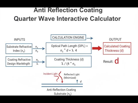
Quarter Wave Anti-Reflection Coating Interactive Visualizer
Change coating thickness and index to see how much reflection you get from destructive interference. This lets you see in real time how canceling the reflected waves at a surface depends on getting those two parameters right.
COATING THICKNESS
99.6 nm
REFLECTANCE
1.3%
IDEAL INDEX
1.23
FIRGELLI Automations — Interactive Engineering Calculators
Quarter-Wave Anti-Reflection Coating Equations
Simple Example
MgF₂ coating (n₁ = 1.38) on standard glass (n₂ = 1.52) in air (n₀ = 1.0), design wavelength 550 nm:
- Coating thickness: d = 550 / (4 × 1.38) = 99.6 nm
- Ideal coating index: √(1.0 × 1.52) = 1.233
- Uncoated reflectance: 4.26% — Coated reflectance: ~1.3%
Quarter-Wave Thickness
Use the formula below to calculate coating physical thickness.
d = λ / (4n₁)
Where:
- d = Physical thickness of coating layer (nm or μm)
- λ = Design wavelength in vacuum (nm)
- n₁ = Refractive index of coating material (dimensionless)
Optimal Coating Index
Use the formula below to calculate the ideal coating refractive index.
n₁ = √(n₀ × n₂)
Where:
- n₁ = Refractive index of coating (dimensionless)
- n₀ = Refractive index of incident medium, typically air (1.0)
- n₂ = Refractive index of substrate material (dimensionless)
For a glass substrate (n₂ = 1.52) in air (n₀ = 1.0), the ideal coating index is n₁ = 1.233. Magnesium fluoride (MgF₂, n = 1.38) is commonly used despite the mismatch because it provides near-optimal performance with excellent durability.
Reflectance at Design Wavelength
Use the formula below to calculate reflectance for a non-ideal coating index.
R = [(n₀n₂ - n₁²) / (n₀n₂ + n₁²)]²
For non-ideal coating index:
- R = Intensity reflectance (fraction, multiply by 100 for percentage)
- When n₁ = √(n₀n₂), reflectance R = 0 (perfect anti-reflection)
- Deviation from ideal index increases residual reflectance quadratically
Wavelength-Dependent Reflectance
Use the formula below to calculate reflectance at wavelengths away from the design center.
R(λ) = [r₀₁² + r₁₂² + 2r₀₁r₁₂cos(δ)]
Where:
- r₀₁ = (n₀ - n₁) / (n₀ + n₁) — Fresnel reflection coefficient at first interface
- r₁₂ = (n₁ - n₂) / (n₁ + n₂) — Fresnel reflection coefficient at second interface
- δ = (4πn₁d cosθ₁) / λ — Phase change upon reflection (radians)
- θ₁ = Refraction angle in coating layer (radians)
At the design wavelength λ₀, the phase shift δ = π, making cos(δ) = -1, which causes destructive interference between reflections from the two interfaces.
Optical Thickness
Use the formula below to calculate optical path difference through the coating.
OPD = n₁ × d
Where:
- OPD = Optical path difference (nm)
- For quarter-wave coating: OPD = λ/4
- Physical thickness decreases with increasing refractive index
Theory & Engineering Applications of Quarter-Wave Anti-Reflection Coatings
Thin-film coatings are a straightforward practical fix to surface reflection losses. At a glass/air interface, expect about 4% reflection even on a single surface because of refractive index mismatch. Multiply that by many optical elements, and you can easily lose a third or more of your light before anything reaches a sensor or image plane. The quarter-wave technique uses a thin film of very specific optical thickness to create destructive interference and cut this loss as much as possible within material limits.
Physical Principles and Interference Mechanics
A quarter-wave anti-reflection coating works by splitting each incoming beam—one portion reflects off the air/coating surface, another travels through and reflects off the interface beneath. By setting the film thickness so the reflected waves travel an extra half wavelength (accounting for phase inversion on reflection), they come out of phase and mostly cancel each other. The optical thickness (index × thickness) needs to be exactly λ/4 at the target wavelength. If your coating index is chosen right (the geometric mean of outside and substrate index), the two reflections are not only 180° out of phase, but also equal in magnitude, giving the best cancellation. That’s the principle; material realities mean you rarely hit the ideal exactly.
Material Selection and Practical Constraints
In practice, you’re usually stuck with materials available, durable, and affordable enough for manufacturing. Magnesium fluoride (MgF₂, n ≈ 1.38) is the standard, even though the perfect index for typical glass in air is 1.23. With this mismatch, you drop surface reflectance from about 4.2% to 1.3%, not zero—but that’s already a big win. Alternatives like porous silica (lower index) get you closer to ideal but are fragile and hard to apply. At higher substrate indices (silicon, germanium), you have to hunt for much higher index coatings—sometimes aluminum oxide or cerium oxide, though it’s rare to find a perfect match for both index and durability.
Wavelength Dependence and Spectral Bandwidth
Single-layer quarter-wave coatings work best only at the design wavelength. Shift even ±10% and reflectance rises quickly, sometimes doubling from the minimum. This is a hard physical limitation: the destructive interference is tuned for a fixed optical path—the farther off your wavelength, the less cancellation you get. For applications that must work across multiple wavelengths (e.g., camera lenses, telecom windows), you’ll need multilayer coatings to stretch that low-reflection region wider. This requires more process control and higher cost.
Angular Dependence and Oblique Incidence Effects
The angle at which light hits the coating matters. At non-normal incidence, the effective optical thickness grows (since the path through the film is longer), so your minimum reflection shifts toward shorter wavelengths than you intended. Also, the reflection behavior starts to depend on polarization (s- and p- polarization reflect differently). For slow systems (narrow cones of light, f/8 and up) this matters little, but once you get to fast lenses (f/2, f/1.4) or wide-acceptance optics, angle effects become real and may require thinner or multi-index coatings to average out the shift.
Worked Example: Designing a Green Laser Anti-Reflection Coating
Take a window for a 532 nm green laser. Use fused silica (n₂ = 1.4607 at 532 nm) and coat it with MgF₂ (n₁ = 1.3777 at 532 nm), in air (n₀ = 1.0).
Step 1: Thickness
d = 532 nm / (4 × 1.3777) = 96.55 nm
Step 2: Optical Thickness
n₁ × d = 1.3777 × 96.55 nm = 133.0 nm (should be λ/4 = 133 nm, so check matches)
Step 3: Ideal Coating Index
Ideal n₁ = √(1.0 × 1.4607) = 1.2086
MgF₂ is about 14% higher than ideal.
Step 4: Residual Reflectance
R = [(1.0 × 1.4607 - 1.3777²) / (1.0 × 1.4607 + 1.3777²)]²
= [1.4607 - 1.8981)/(1.4607 + 1.8981)]²
= (-0.4374 / 3.3588)² = 0.01695 or 1.70%
Step 5: Baseline Uncoated Reflectance
R₀ = [(1.0 - 1.4607) / (1.0 + 1.4607)]² = 0.03507 or 3.51%
Result: The MgF₂ coating cuts reflectance from 3.51% to 1.70%. Not perfect, but that’s a 51% drop. Getting any closer would require either better material matching (usually not available), multilayer films, or accepting a more expensive and fragile solution. Precision in thickness (down to about ±2 nm) matters if you want these numbers to hold in production; modern coating tools can do this by monitoring optical response in real time rather than trusting mechanical thickness alone.
Manufacturing Considerations and Deposition Technologies
Most quarter-wave coatings are laid down by physical vapor deposition: usually electron-beam evaporation or ion-beam sputtering. E-beam is fast and efficient for high volumes, but the biggest challenge is keeping thickness in spec—small process errors or density shifts in the film change optical performance. Reliable production now relies on optical monitoring as you deposit, rather than only measuring deposited thickness with a crystal monitor or caliper. Ion-assist steps can densify coatings, though at slower rates and higher complexity, but improve long-term durability, especially for outdoor or high-power laser work.
For more resources on optics and engineering, including calculators for lens design and photometry, visit the engineering calculator library.
Practical Applications
Scenario: Camera Lens Manufacturing Quality Control
Jennifer is checking a production batch of objective lenses for a 50mm f/1.4 camera. Each lens has 14 coated glass surfaces, with quarter-wave MgF₂ at 550 nm. A thickness measurement comes out at 99.82 nm on BK7 (n = 1.519 @ 550 nm). The calculator shows 1.31% reflectance per surface instead of the uncoated 4.26%. Over all 14 surfaces, total transmission is 82.1% versus just 54.3% uncoated—enough to meet an >80% spec and justify the time and cost for this coating.
Scenario: Solar Panel Efficiency Optimization
Marcus is improving anti-reflection coatings for silicon solar cells. Bare silicon (n ≈ 3.88 at 600 nm) reflects about 35%. Using the calculator with air (n₀ = 1.0) and silicon (n₂ = 3.88), the ideal coating index comes out as 1.97. He picks silicon nitride (n = 2.05), which is close enough and practical. Required thickness is 73.17 nm for 600 nm wavelength. The coating keeps reflectance below 5% across most of the solar spectrum (450–750 nm), which boosts efficiency by nearly 3% absolute—a major difference for real-world solar installation payback.
Scenario: Laser Safety Window Design
Kenji needs a laser observation window for a wafer fab using 193 nm ArF excimer lasers. Window is fused silica (n = 1.5076 at 550 nm) with MgF₂ coating (n = 1.38), optimized for 550 nm for best visible transmission. Calculator shows 99.64 nm coating gives minimum reflection at 550 nm; but at 193 nm, the same film creates higher (8.3%) reflection—which in this twist is beneficial, adding extra UV protection. He gets high transmission for visible work and built-in UV blocking at the laser wavelength, without needing separate filters.
Frequently Asked Questions
Why doesn't a quarter-wave coating eliminate all reflection? +
How do I choose the design wavelength for my application? +
What happens to coating performance at angles other than normal incidence? +
Can quarter-wave coatings be used in the ultraviolet or infrared regions? +
How does coating thickness tolerance affect performance? +
Why does my coated optic show colored reflections instead of appearing uniformly dark? +
Free Engineering Calculators
Explore our complete library of free engineering and physics calculators.
Browse All Calculators →🔗 Explore More Free Engineering Calculators
About the Author
Robbie Dickson — Chief Engineer & Founder, FIRGELLI Automations
Robbie Dickson brings over two decades of engineering expertise to FIRGELLI Automations. With a distinguished career at Rolls-Royce, BMW, and Ford, he has deep expertise in mechanical systems, actuator technology, and precision engineering.
Need to implement these calculations?
Explore the precision-engineered motion control solutions used by top engineers.


