When you’re planning a retaining wall, sheet pile, or basement wall, you have to get your earth pressure estimates close to reality. If you guess low, you risk failure. Overshoot, and you add unnecessary concrete and cost. The Active Earth Pressure Rankine Calculator here lets you figure out the pressure profile, total force, and overturning moments using wall height, soil weight, friction angle, cohesion, and surface loads. You’ll see the Rankine formulas, a worked example, plain engineering theory, and a Q&A section. This isn’t just for geotechnical specialists—engineers dealing with foundations, marine projects, or underground construction will run into these numbers sooner or later.
What is Active Earth Pressure?
Active earth pressure is the sideways push from soil against a wall when the wall moves a little away from the soil. This is the minimum lateral force the ground can muster as the soil relaxes—it’s the value you must cover if you want your wall to keep standing over time.
Simple Explanation
Picture a row of books leaning on a bookend. If you nudge the bookend outward, the books push sideways with a known force—that’s your active earth pressure. Denser or heavier “books” (the soil) push harder. Rankine’s approach just gives you a formula to tie soil properties and wall movement to an actual pressure number, so you can work out how much wall you need.
📐 Browse all 1000+ Interactive Calculators
Table of Contents
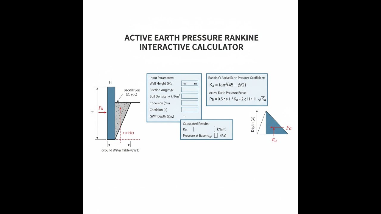
Retaining Wall Diagram

Active Earth Pressure Rankine Calculator
How to Use This Calculator
This calculator is intended for education, concept evaluation, and preliminary design. Results are based on the equations and assumptions described on this page, but cannot account for every real-world load case, tolerance, material property, environmental condition, installation detail, safety factor, code, or regulatory requirement. Verify all inputs, assumptions, units, and results independently before selecting components or using the result in a real application. Safety-critical, structural, medical, lifting, transportation, or regulated applications must be reviewed by a qualified engineer.
- Pick which variable you want to solve for—pressure curve, total force, overturning moment, Ka coefficient, required height, or required soil density.
- Type in your known values: wall height (m), soil unit weight (kN/m³), friction angle (degrees), cohesion (kPa), and any surcharge at the surface, depending on what you’re solving.
- Validate your numbers before calculating: friction angle has to be between 0° and 90°, and all weights and heights must be positive.
- Hit Calculate.
Active Earth Pressure Rankine Interactive Calculator
If you want to see how pressure against a wall varies with depth, you can adjust the wall height, soil properties, or surface load here. Use this to visualize how the forces change before heading to detailed design.
Ka COEFFICIENT
0.333
MAX PRESSURE
24.0 kPa
RESULTANT FORCE
48.0 kN/m
MOMENT ARM
1.33 m
FIRGELLI Automations — Interactive Engineering Calculators
Equations & Formulas
Below is the direct formula for the Rankine active earth pressure coefficient:
Active Earth Pressure Coefficient (Rankine):
Ka = tan²(45° - φ/2)
Lateral Earth Pressure at Depth z:
σa = Ka(γz + q) - 2c√Ka
Resultant Active Force (per unit width):
Pa = ½KaγH² + KaqH - 2c√KaH
Location of Resultant Force (from base):
z̄ = H/3 × (2σbottom + σtop) / (σbottom + σtop)
Overturning Moment about Base:
M = Pa × z̄
Where:
- Ka = Active earth pressure coefficient (dimensionless)
- φ = Internal friction angle of soil (degrees)
- σa = Active lateral earth pressure at depth z (kPa)
- γ = Unit weight of soil (kN/m³)
- z = Depth below ground surface (m)
- H = Total height of retaining wall (m)
- q = Uniform surcharge load at surface (kPa)
- c = Soil cohesion (kPa)
- Pa = Total active force per unit width of wall (kN/m)
- z̄ = Height of resultant force location above base (m)
- M = Overturning moment about wall base (kN·m/m)
Simple Example
Let’s check the calculations for a 4 m wall holding up dry sand (γ = 18 kN/m³, φ = 30°, c = 0, no surcharge):
- Ka = tan²(45° − 15°) = tan²(30°) = 0.333
- Pressure at the base: σₐ = 0.333 × 18 × 4 = 24.0 kPa
- Total active force: Pₐ = ½ × 0.333 × 18 × 4² = 48.0 kN/m, acting 1.33 m above the base
Theory & Engineering Applications
Rankine’s theory (1857) is still a go-to method in geotechnical engineering for getting a first pass on lateral soil pressures. It predicts the lowest stable pressure developed if the soil behind a wall is allowed to move enough for a shear failure wedge to form. That critical wedge slips at an angle of 45° plus half the internal friction angle of the soil. This isn’t a modern “black box” soil model—it’s a straightforward envelope and stress solution, and it holds up well if used carefully.
Fundamental Assumptions and Limitations
Rankine assumes the soil mass stretches out infinitely back from the wall, the back of the wall is vertical, soils don’t change with depth, and the surface above the wall is flat or uniformly sloped. The calculation only makes sense if the wall moves far enough for the soil to fail along its weakest path. For sand, this means a 5 m wall only needs to lean out about 5–20 mm from its original position before the active pressure is fully “mobilized.” In stiffer clays or for massive walls, this movement can be much more, and sometimes the wall never moves enough to justify active pressure assumptions at all.
Rankine assumes no friction between the wall and the soil—basically, a polished wall. In real life, concrete or block walls develop some friction, which slightly lowers the actual force compared to the Rankine estimate. That means you’ll generally get a conservative (high) number from this approach. If you know the wall-soil friction, Coulomb gives you a closer estimate, but it’s a more involved formula and not always possible if site interface data isn’t handy. Because Rankine is simple and conservative, it’s still used early in design, or when you need to know you’re not underestimating.
Active Earth Pressure Coefficient Derivation
The Rankine coefficient, Ka, comes out of a basic Mohr’s circle analysis of the soil’s failure state. Here, vertical stress is from gravity, and horizontal stress is what presses on the wall. The circle’s tangency to the failure envelope at just the right point spits out Ka = tan²(45° - φ/2). As φ increases, Ka drops sharply. That means small differences in your measured soil friction angle make a big change in calculated wall forces. If you’re overestimating soil strength, you’re one step from trouble.
This formula is sensitive to friction angle—each 5-degree error can skew lateral forces by 15–20%. That’s why field or lab testing (triaxial or direct shear) for φ is worth the trouble if you want to avoid wasting concrete or risking a wall collapse.
Cohesion Effects and Tension Zone Formation
Soil cohesion, if present, subtracts from the pressure at every depth—sometimes so much that negative (tensile) pressures show up near the top of the wall. Soil can’t take tension, so a crack forms to the depth where lateral stress goes to zero; below that, it’s “in compression” again. For many real clays, tension cracks will reach 1.5 to 3 meters deep in average conditions. If water fills that crack, hydrostatic pressure is added directly against the wall, often overwhelming any gain from cohesion. Because of these risks, any benefit from soil cohesion is usually ignored (c = 0) in permanent wall design, except sometimes in temporary works.
Applications Across Engineering Disciplines
Basement walls are a typical case for Rankine active pressure. For a 3-meter deep basement with sandy backfill (γ = 19 kN/m³, φ = 35°), you get a total horizontal force of around 46 kN/m, applied about 1m up from the base. That figure is what you check your footings and reinforcement against. In coastal projects, you use the soil’s submerged weight below water level—often about half the dry weight—to reduce the pressure numbers for bulkheads or sea walls. For sheet piling, the pressure profile can drop by 70% between dry and fully submerged sand—a design factor that can change your project’s cost and pile driving requirements by a wide margin.
Mining and excavation projects also rely on these methods. When building shoring in a pit or staging excavation depths, knowing how much lateral support the walls need at every stage comes back to Rankine-type calculations, especially when using simple trench supports or sheet piles in cities or close quarters where fully mobilizing wall movement isn’t always possible.
Worked Example: Basement Retaining Wall Design
Let’s work through a practical case:
- Wall height H = 4.2 meters
- Backfill, medium sand: γ = 18.5 kN/m³
- Internal friction angle φ = 32° (lab result)
- Cohesion c = 0 kPa (typical for granular backfill)
- Surcharge q = 12 kPa (landscaping or vehicle loading)
Step 1: Active Earth Pressure Coefficient
Ka = tan²(45° - φ/2) = tan²(45° - 16°) = tan²(29°) = (0.5543)² = 0.3073
Step 2: Pressure Profile
At surface (z = 0):
σₐ(top) = Ka × q = 0.3073 × 12 = 3.69 kPa
Base (z = 4.2):
σₐ(bottom) = Ka(γH + q) = 0.3073(18.5 × 4.2 + 12) = 0.3073 × 89.7 = 27.56 kPa
Step 3: Resultant Force
This profile is a trapezoid, so:
Pₐ = ½(σₐ(top) + σₐ(bottom)) × H = ½ × (3.69 + 27.56) × 4.2 = 65.63 kN/m
Step 4: Resultant Height
Resultant force acts at:
z̄ = H/3 × (2σₐ(bottom) + σₐ(top))/(σₐ(bottom) + σₐ(top))
= 4.2/3 × (2 × 27.56 + 3.69)/(27.56 + 3.69) ≈ 2.63m above the base.
This is higher than the usual H/3 for a triangle, showing how a surcharge pushes the resultant force up the wall.
Step 5: Overturning Moment
M = Pₐ × z̄ = 65.63 × 2.63 = 172.6 kN·m per meter run
Step 6: Structural Check
Compare that overturning moment to what your wall and footing can resist. For a standard 0.4m thick cantilever wall with 3m footing and concrete at 24 kN/m³, calculated resistance might be 240 kN·m/m. That’s an overturning safety factor of 1.39—not enough. So you’d have to either widen the footing, increase soil strength by compaction, or add reinforcement. These calculations quickly show what’s driving your cost and sizing at early stages.
Changing footing width by even a meter could mean big added cost in concrete and excavation, so accurate soil tests and correct parameter use matter for both price and performance.
Integration with Modern Design Codes
Guidelines like AASHTO LRFD and Eurocode 7 still build Rankine-style active pressure into their load formulas. They apply “partial factors” to the soil numbers and forces, so you add a layer of safety for uncertainty in both loads and soil strength. Usually, these codes tell you to drop the friction angle by a few degrees or bump up the force by 20–50% over the raw calculation to give a margin for error. When using advanced numerical modeling (e.g., finite elements), most engineers still check that their results are in the same ballpark as Rankine. If your pile or wall needs fancy analysis, but your Rankine force is way off your model, that’s a red flag you’ve mis-stepped somewhere.
Practical Applications
Scenario: Residential Basement Waterproofing Design
A structural engineer is detailing a 3.6-meter-deep basement in sandy soil. There’s an extra 0.6 meters of landscaping and topsoil loading the wall—8 kPa more surcharge. Using the calculator with γ = 17.8 kN/m³, φ = 31°, Marcus gets earth pressures of 2.4 kPa at the top and 22.7 kPa at the base, and a resultant of 45.2 kN/m at 1.26 meters up. That drives a design with 250mm thick walls and #5 bar at 300mm, and a 2.8m footing to hit a 2.5 overturning safety factor. The main lesson: never skip accounting for surcharges, or you risk the sort of wall cracking and leaks that happen in a lot of basements with landscaping above.
Scenario: Highway Retaining Wall Cost Optimization
A transportation consultant checks a 6.5m tall highway wall, comparing MSE reinforcement cost to a cast-in-place cantilever. Site data shows dense sand (γ = 19.2 kN/m³, φ = 37°). With a 15 kPa traffic surcharge, the Ka value drops to 0.249 versus the usual default of 0.33, so the wall force is well within cantilever design limits. Numbers from the calculator let the team confidently switch to a cheaper construction type, saving over $1 million on a 450m wall stretch. Better field data and more accurate pressure numbers often mean direct budget wins like this, without reducing reliability.
Scenario: Forensic Investigation of Wall Failure
A 4m retaining wall collapsed during rain. Design called for sand with φ = 35° (82 kN/m calculated). Inspection showed silty sand—actual φ closer to 28°, and the soil saturated during failure. Plugging the real values into the calculator gives 119 kN/m, almost 50% more force. Add water in the unseen tension crack: another 20 kN/m that wasn’t considered. The wall’s failure came down to underestimating the soil’s real friction angle, ignoring potential hydrostatic buildup, and not matching actual site conditions to design assumptions. Small soil parameter changes can mean major real-world effects. Field checks and drainage matter.
Frequently Asked Questions
▼ What is the difference between active and passive earth pressure, and when does each occur?
▼ Why do Rankine and Coulomb methods sometimes give different results, and which should I use?
▼ How do I account for groundwater in active earth pressure calculations?
▼ Should I include cohesion in my active pressure calculations for clay soils?
▼ How do I determine if my retaining wall has moved enough to reach the active pressure condition?
▼ What safety factors should be applied when using Rankine active pressure calculations in design?
Free Engineering Calculators
Explore our complete library of free engineering and physics calculators.
Browse All Calculators →🔗 Explore More Free Engineering Calculators
About the Author
Robbie Dickson — Chief Engineer & Founder, FIRGELLI Automations
Robbie Dickson brings over two decades of engineering expertise to FIRGELLI Automations. With a distinguished career at Rolls-Royce, BMW, and Ford, he has deep expertise in mechanical systems, actuator technology, and precision engineering.
Video Walkthrough - How to Use This Calculator
Need to implement these calculations?
Explore the precision-engineered motion control solutions used by top engineers.


