Every analog circuit runs into a wall eventually — not because of component quality or layout, but because of unavoidable thermal noise. Johnson-Nyquist noise comes from the random thermal motion of electrons inside resistors. If you’re designing anything low-noise, you need to know this limit; guessing gets you in trouble. This Resistor Noise Interactive Calculator gives you thermal noise spectral density, integrated noise voltage, SNR, and equivalent noise temperature based on resistance, temperature, and bandwidth. You’ll encounter this in lab-grade measurement equipment, amplifier inputs, and real-world sensor front-ends wherever noise sets your resolution floor. The content below includes core equations, an example using thermocouples, engineering details, and an FAQ.
What is resistor thermal noise?
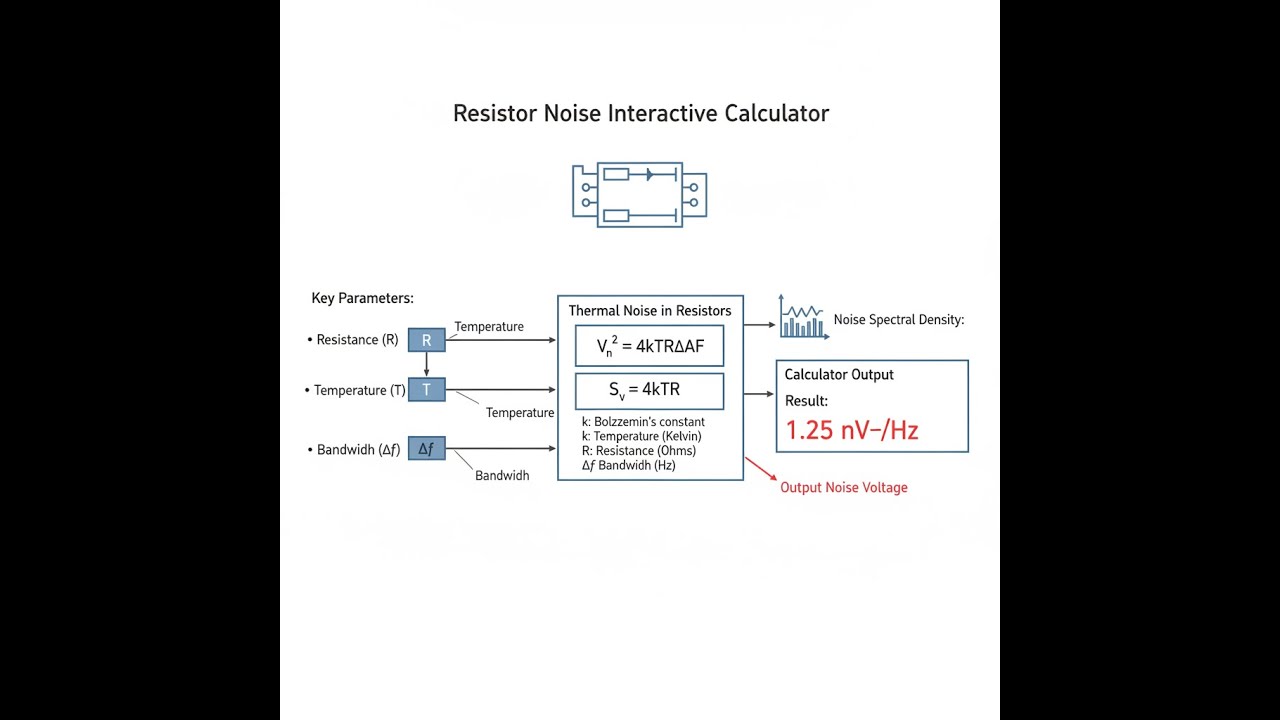
Resistor thermal noise—Johnson-Nyquist noise—is the unavoidable random voltage that shows up across any resistor, just because it’s warm. The higher the resistor value or the bandwidth, the more noise you get. It puts a floor under how quiet your circuit can be, no matter what else you do.
Simple Explanation
Inside a resistor, electrons are in constant random motion—as if there’s always a little jostle going on. That motion, even with no current flowing, causes unpredictable voltage wiggles across the resistor’s ends. Bigger resistor or hotter temperature means more agitation, so the noise voltage you measure gets larger too.
📐 Browse all 1000+ Interactive Calculators
Noise Voltage Diagram

How to Use This Calculator
- Pick your calculation from the dropdown list—options include total noise voltage, spectral density, bandwidth, max resistance, SNR, or equivalent noise temperature.
- Type in your numbers: resistance (Ω), temperature (K), bandwidth (Hz), signal voltage, or measured noise density, as needed for your selected calculation.
- You can use the Try Example button to load some practical values.
- Click Calculate and read the results.
Interactive Resistor Noise Calculator
This calculator is intended for education, concept evaluation, and preliminary design. Results are based on the equations and assumptions described on this page, but cannot account for every real-world load case, tolerance, material property, environmental condition, installation detail, safety factor, code, or regulatory requirement. Verify all inputs, assumptions, units, and results independently before selecting components or using the result in a real application. Safety-critical, structural, medical, lifting, transportation, or regulated applications must be reviewed by a qualified engineer.
Resistor Noise Interactive Visualizer
See in real time how resistance, temperature, and bandwidth push up thermal noise. Tweak the parameters—watch how Johnson-Nyquist noise changes and visualize what happens to the magnitude and frequency spread on the spot.
SPECTRAL DENSITY
12.87 nV/√Hz
TOTAL NOISE
0.41 µV
PEAK-TO-PEAK
2.45 µV
FIRGELLI Automations — Interactive Engineering Calculators
Governing Equations
Simple Example
A 10 kΩ resistor at room temperature (298 K) with a 1 kHz bandwidth:
- Noise spectral density: √(4 × 1.381×10⁻²³ × 298 × 10000) = 12.87 nV/√Hz
- Total integrated noise: 12.87 nV/√Hz × √1000 = 0.407 µVRMS
- Peak-to-peak noise (6σ): 0.407 × 2√2 = 1.15 µVPP
Thermal Noise Spectral Density
Use the formula below to calculate thermal noise spectral density.
en = √(4kBTR)
Where:
- en = Noise voltage spectral density (V/√Hz)
- kB = Boltzmann constant = 1.380649 × 10⁻²³ J/K
- T = Absolute temperature (K)
- R = Resistance (Ω)
Total Integrated Noise Voltage
Use the formula below to calculate total integrated noise voltage.
vn,RMS = en √Δf = √(4kBTRΔf)
Where:
- vn,RMS = Total RMS noise voltage (VRMS)
- Δf = Noise bandwidth (Hz)
Signal-to-Noise Ratio
Use the formula below to calculate signal-to-noise ratio.
SNRdB = 20 log10(Vsignal / vn,RMS)
Where:
- SNRdB = Signal-to-noise ratio (decibels)
- Vsignal = RMS signal voltage (VRMS)
- vn,RMS = RMS noise voltage (VRMS)
Equivalent Noise Temperature
Use the formula below to calculate equivalent noise temperature.
Teq = en2 / (4kBR)
Where:
- Teq = Equivalent noise temperature (K)
- en = Measured noise spectral density (V/√Hz)
Theory & Practical Applications
Resistor noise is the baseline limit for how finely you can measure voltage or current in any circuit. Unlike most noise—which you can minimize with better layout or components—thermal noise (Johnson-Nyquist) is set by physics and temperature. Knowing how to estimate this noise lets you spot if you’re chasing your tail for improvements. This matters most when you’re working at the noise floor: high-precision lab instruments, amplifier input stages, and direct sensor readout circuits.
Physical Origin of Thermal Noise
Every resistor generates noise because the electrons inside never stop moving unless you cool it to absolute zero. The random movement isn’t about poor manufacturing; it’s just Brownian motion played out with electrons rather than molecules. These fluctuations show up as a voltage between the resistor’s ends, even without applied current. If you measure the spectrum, thermal noise stays flat (white) until you hit extremely high frequencies (approaching an optical wavelength)—well past most practical circuit frequencies. Every hertz of bandwidth brings in a little more noise, and those contributions add up independently across frequency (that’s why noise voltage scales with the square root of bandwidth).
The “4” in the equation comes from accounting for both real and imaginary impedance, and the two directions (positive and negative frequencies) when working from the fundamental derivation. The voltage noise only scales with the square root of resistance: double the resistance, and noise goes up by only about 41%, not by a factor of two. That’s important—high-value resistors aren’t as much noisier as beginners sometimes expect, but current noise from circuits becomes a bigger deal as you go up in resistance because it adds linearly, not as a square root.
Bandwidth Dependence and Integration
Integrated noise always depends on the square root of bandwidth because you’re summing the power, not the amplitudes, across frequencies. In theoretical math, a “brick-wall” filter has a perfect cutoff, so all the frequencies between f1 and f2 matter equally, none outside. Real filters don’t do that—they slope off. For a simple RC low-pass (single-pole), the effective noise bandwidth is about 1.57 times the -3 dB (corner) frequency. A 2nd-order Butterworth gets closer to the ideal, at about 1.11× the -3 dB bandwidth. Use the wrong bandwidth in calculation, and you could be off by up to 30% or more. This is critical if you’re working at microvolt noise levels.
One important reality: the noise bandwidth is set by every capacitance and inductance (intended or stray) before your measurement stage. So, high source resistance and any stray capacitance easily form a low-pass filter that often dominates your actual measurement bandwidth, and sets your integrated noise—sometimes much more than you’d expect from your schematic alone. This is why precision designers worry about PCB layout, input filtering, and minimizing stray capacitance near critical resistors and amplifiers.
Temperature Effects and Thermal Management
If you want less noise, lowering temperature is a straightforward way—noise voltage drops with the square root of temperature. For most bench circuits, cooling from room temperature to cryogenic levels (like using liquid nitrogen) can cut noise about in half. Liquid helium gets you about a 4-times improvement. But that’s only worthwhile if thermal noise is actually your dominant problem, and managing power or other noise mechanisms (like shot noise and 1/f noise) at low temperatures becomes a different challenge. In real use, only a few systems (like fundamental physics labs or radio telescopes) cool all the way down for noise reasons.
A resistor’s actual noise temperature depends not only on the air temperature, but also on self-heating—how hot it gets when current flows through it. A resistor dissipating even a few milliwatts in a small package can run 20°C hotter than the ambient environment, adding about 5% more noise. For high-precision analog work, pick resistor packages with enough surface area and thermal connection to keep the self-heating minimal, or spread the power over more than one resistor.
Worked Engineering Example: Precision Thermocouple Interface
Suppose you want high-precision temperature readings from a Type K thermocouple (41 µV/°C), typical resistance 20 Ω. The system must resolve 0.01°C and has a measurement bandwidth of 2 Hz. You want to know if resistor thermal noise gets in the way.
Given Parameters:
- Thermocouple Seebeck coefficient: S = 41 µV/°C
- Source resistance: Rsource = 20 Ω
- Ambient temperature: T = 298.15 K (25°C)
- Measurement bandwidth: Δf = 2 Hz
- Target resolution: 0.01°C
- Amplifier input resistance: Ramp = 10 MΩ (negligible loading)
Step 1: Calculate Required Voltage Resolution
To resolve a 0.01°C step: 41 µV × 0.01 = 0.41 µV. Your measurement electronics need to see voltage changes down to this scale, or you don’t get the needed temperature resolution.
Step 2: Calculate Thermocouple Thermal Noise
Noise spectral density: √(4 × 1.380649×10-23 × 298.15 × 20) ≈ 1.814 nV/√Hz
Integrated RMS noise over 2 Hz: 1.814 nV × √2 ≈ 2.565 nV
Step 3: Equivalent Temperature Noise
2.565 nV / 41 µV/°C ≈ 0.0000626°C, or 62.6 µK. This is much lower than your 0.01°C (10,000 µK) target.
Step 4: System Noise Budget Analysis
Amplifier voltage noise still matters. Assume a low-noise amplifier with 5 nV/√Hz; its noise over 2 Hz is 5 × √2 ≈ 7.07 nV (RMS). Amplifier current noise on a 20 Ω source is tiny. Sum resistor and amplifier noise in quadrature: √(2.565² + 7.07²) ≈ 7.52 nV. Temperature noise: 7.52 nV / 41 µV/°C ≈ 0.000183°C (0.183 mK). Still well under 0.01°C.
Step 5: SNR and Effective Bits
The SNR for a 41 mV range: 20 log10(0.041 / 7.52e-9) = 134.7 dB.
ENOB: (134.7 - 1.76) / 6.02 ≈ 22.1 bits.
Conclusion:
In this setup, resistor noise is only a small fraction of your noise budget. You’ll hit amplifier noise, 1/f noise, thermocouple EMFs, and interference before resistor noise limits you. However, if your sensor had a much higher resistance, or if you let self-heating raise the temperature, the numbers could shift enough to matter.
Practical Design Considerations
Picking resistors in low-noise analog circuits is always a compromise between noise, temperature stability, and cost. Metal film resistors are quieter than carbon types when it comes to 1/f noise, but they still give you white (thermal) noise set by resistance, temperature, and bandwidth. If you’re chasing noise floors below 100 Hz, thin-film or wirewound resistors generally do better, at the cost of size and sometimes extra inductance. For a 10 kΩ thin-film resistor at room temperature, you don’t get lower than about 13 nV/√Hz. This is your baseline for any circuit with that resistance in the signal path.
If you put two equal-value resistors in parallel, the total resistance halves, but the combined noise voltage is the same as a single resistor of that parallel value. Sometimes designers use parallel combinations when they can’t source the exact value needed or to spread power dissipation, but it’s not a way to "cheat" the noise limit. On the other hand, differences in resistor 1/f noise and voltage coefficient do show up in parallel arrangements.
For more precision electronics calculators, visit the FIRGELLI Engineering Calculator Hub.
Frequently Asked Questions
Free Engineering Calculators
Explore our complete library of free engineering and physics calculators.
Browse All Calculators →🔗 Explore More Free Engineering Calculators
- I2C/SPI Bus Speed & Pull-up Resistor Sizing
- Capacitor Charge Discharge Calculator — RC Circuit
- Wheatstone Bridge Calculator
- RLC Circuit Calculator — Resonance Impedance
- Free Space Path Loss Calculator
- Capacitors In Series Calculator
- Spherical Capacitor Calculator
- Power Factor Calculator and Correction
- Voltage Divider & ADC Resolution Calculator
- Voltage Divider Calculator
About the Author
Robbie Dickson — Chief Engineer & Founder, FIRGELLI Automations
Robbie Dickson brings over two decades of engineering expertise to FIRGELLI Automations. With a distinguished career at Rolls-Royce, BMW, and Ford, he has deep expertise in mechanical systems, actuator technology, and precision engineering.
Video Walkthrough - How to Use This Calculator
Need to implement these calculations?
Explore the precision-engineered motion control solutions used by top engineers.


