When you expose a crystal to X-rays, the atoms act like a series of reflectors. Scattered X-rays will only reinforce each other at certain angles, producing clear diffraction peaks you can actually measure. If you get the angle wrong, the scattered waves just cancel each other out and there's no peak at all. X-ray crystallography relies on finding these constructive angles. The Bragg's Law calculator here helps you solve for wavelength, lattice spacing, diffraction angle, or diffraction order using the basic nλ = 2d sin θ relationship. This law is immediately useful in fields like semiconductor inspection, checking polymorphs in drugs, or phase analysis in metals. On this page you'll find the formula breakdown, a practical silicon example, coverage of lattice planes and X-ray sources, and an FAQ focused on typical lab and industry issues.
What is Bragg's Law?
Bragg's Law tells you at which angle a beam of X-rays (or similar particles) will diffract off parallel atomic planes in a crystal. If you set up at just the right angle, the scattered waves build up together and give you a strong diffraction peak. That peak tells you directly about the spacing between the crystal planes.
Simple Explanation
Imagine a crystal as a stack of super-thin mirrors with tiny gaps between them. When X-rays shine on this stack, some rays reflect off the top mirror, others off mirrors deeper inside. Depending on the angle, these reflected rays either add together or cancel out. Bragg's Law just tells you the exact angle where the rays reinforce—then you can use that angle to figure out how far apart the mirror-like layers are.
📐 Browse all 1000+ Interactive Calculators
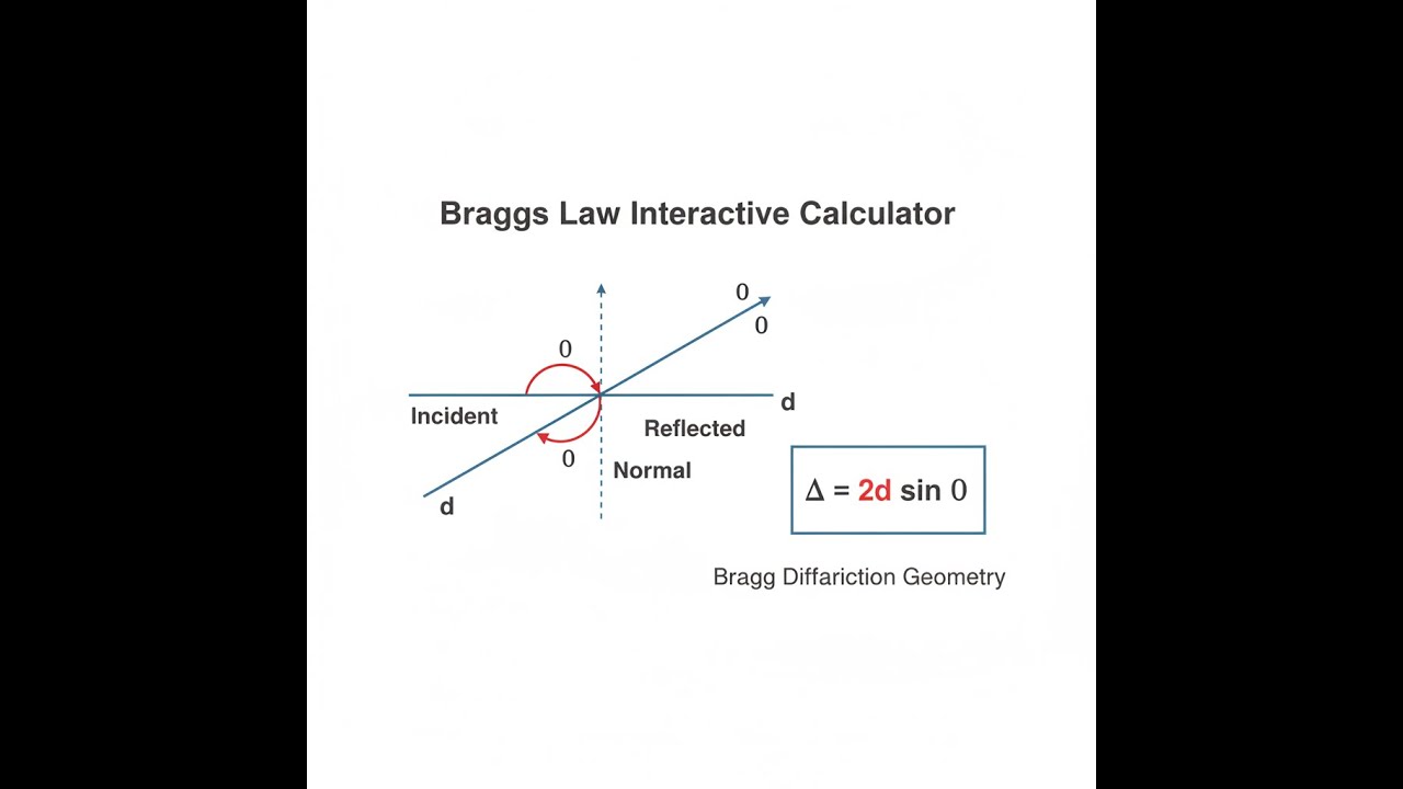
Bragg Diffraction Diagram

How to Use This Calculator
- Select your calculation mode from the dropdown — choose whether you want to solve for wavelength, lattice spacing, diffraction angle, order number, or maximum order.
- Enter the known values into the visible input fields: order (n), wavelength (λ) in Angstroms, lattice spacing (d) in Angstroms, and/or Bragg angle (θ) in degrees, as required by your selected mode.
- Check your inputs — order must be a positive integer, angle must be between 0° and 90°, and all physical quantities must be positive.
- Click Calculate to see your result.
Bragg's Law Calculator
This calculator is intended for education, concept evaluation, and preliminary design. Results are based on the equations and assumptions described on this page, but cannot account for every real-world load case, tolerance, material property, environmental condition, installation detail, safety factor, code, or regulatory requirement. Verify all inputs, assumptions, units, and results independently before selecting components or using the result in a real application. Safety-critical, structural, medical, lifting, transportation, or regulated applications must be reviewed by a qualified engineer.
Bragg's Law Interactive Visualizer
Change the diffraction parameters and you'll see how the nλ = 2d sin θ relationship controls the angle for constructive interference in crystals. Adjusting the values is the quickest way to get a practical feel for how the key variables interact, beyond just the formulas.
BRAGG ANGLE
14.5°
DETECTOR ANGLE
29.0°
PATH DIFF
1.54 Å
FIRGELLI Automations — Interactive Engineering Calculators
Bragg's Law Equations
Below is the working formula you’ll use when applying Bragg’s Law.
Fundamental Bragg Condition
nλ = 2d sin θ
where:
- n = order of diffraction (positive integer: 1, 2, 3...)
- λ = wavelength of incident radiation (Angstroms, Å)
- d = interplanar spacing (lattice spacing between parallel planes, Å)
- θ = Bragg angle (angle between incident beam and crystal planes, degrees or radians)
Derived Relations
Wavelength Calculation:
λ = (2d sin θ) / n
Lattice Spacing Calculation:
d = nλ / (2 sin θ)
Bragg Angle Calculation:
θ = arcsin(nλ / 2d)
Maximum Order Condition:
nmax = floor(2d / λ)
Since sin θ ≤ 1, the maximum order is limited by the ratio of lattice spacing to wavelength
Detector Angle (Scattering Angle)
2θ = 2 × θBragg
The detector angle (2θ) is the total scattering angle measured in X-ray diffraction experiments, equal to twice the Bragg angle. This is the angle between the incident beam direction and the scattered beam direction.
Simple Example
Given: n = 1, λ = 1.54 Å (Cu Kα), d = 2.82 Å
Calculate θ: sin θ = (1 × 1.54) / (2 × 2.82) = 0.2730, so θ = arcsin(0.2730) = 15.84°
Detector reads: 2θ = 31.68°
Result: The diffraction peak appears at a detector angle of 31.68°.
Theory & Practical Applications
Physical Basis of Bragg Diffraction
Bragg's Law comes directly from how X-rays or similar waves scatter off regularly spaced planes of atoms in a crystal. The main thing to remember is that constructive interference (a strong signal) only happens if the extra path length for X-rays reflecting off deeper planes equals a whole number of wavelengths. That’s the “2d sin θ” in the formula. If you’re off that integer match, the scattered waves get out of phase and just wash each other out at the detector. In the real world, each atom acts as a scatterer, so the simple “perfect mirror” model ignores a lot. Still, the core result—nλ = 2d sin θ—holds up well for most straightforward setups.
The X-rays penetrate the crystal and reflect from many planes at once. Only at certain angles does the condition for constructive addition hold, and only then do you get a strong diffracted beam. The angle θ here is measured from the plane—the geometry is not always the same as in optics and tends to trip up newcomers. If you use the normal by accident, you’ll end up with the wrong d-spacing.
Lattice Planes and Miller Indices
The spacing d in Bragg's Law is between a particular set of crystal planes, generally labeled by Miller indices (hkl). For a cubic crystal of size a, it's dhkl = a/√(h² + k² + l²). Take silicon with a = 5.431 Å: for (111) planes, d = 5.431/√3 = 3.136 Å; for (220), d = 5.431/√8 = 1.920 Å. The same crystal has a family of plane spacings and each set will diffract at a different angle. Higher index planes (large h, k, l) mean smaller d and diffraction at higher angles.
If your crystal isn't cubic, things get messier—calculating d then means dealing with several lattice constants and angles. For instance, hexagonal lattices need four-index labels and separate a and c distances. That's why manual calculations are rarely practical for these structures and most people let software handle the grunt work for anything but the simplest cases.
Order Number and Higher-Order Reflections
The diffraction order n in Bragg's Law shows up when the path length difference is exactly n wavelengths. First order (n=1) is always at the lowest angle. Second order (n=2) on planes with spacing d produces a peak at the same angle as first order (n=1) for planes spaced at d/2. Because of that, crystallographers often stick to n=1 and just relabel the higher orders as different planes; it's not possible to distinguish them based on the angle alone. You can't observe orders above the maximum given by nmax = floor(2d/λ). If the material's crystal symmetry forbids a reflection (systematic absences), you won't see that peak at all—common in FCC or diamond cubic structures, for example.
You may technically have a “mathematical” solution for a high n, but unless the material’s structure allows it and the sin θ ≤ 1 condition is met, you won’t see anything in your data. High-order peaks are usually quite weak, anyway, and often fall below noise level unless you're using very intense sources or long counting times.
Wavelength Selection and Radiation Sources
Most standard X-ray diffractometers use characteristic lines: Cu Kα (λ = 1.5406 Å), Mo Kα (λ = 0.7107 Å), or Cr Kα (λ = 2.2909 Å). The choice sets what d-spacings and angles you can actually access: shorter wavelengths (like Mo) let you probe smaller spacings or observe more diffraction orders, but push peaks to lower angles with less resolution. Cu Kα usually works best for many structures because it balances penetration, angular spacing, and usable detector range.
Synchrotron sources give you control over wavelength (typically 0.4 to 2.5 Å) and much higher intensity. This lets you do real-time studies, beam focusing for tiny samples, and push weak signals above background without excessive waiting. Neutron diffraction (λ ≈ 1-2 Å) works on a similar principle but probes nuclei, not electron clouds, so is better for finding light atoms hidden among heavy ones and for magnetic structure studies. Each source and wavelength shifts what, and how well, you can measure.
Angular Resolution and Experimental Geometry
The Bragg angle θ is the one in the equations, between the X-ray beam and the crystal planes. In the lab, most diffractometers measure 2θ, which is the total angle between the incoming and outgoing beam. Always double-check which angle your instrument reports; confusing θ and 2θ is a common lab mistake and instantly messes up d-spacing calculations. Most powder diffractometers (Bragg-Brentano geometry) are set up so rotating the sample by θ moves the detector by 2θ, keeping everything focused as you scan through angles.
Diffraction peaks aren't infinitely sharp—width (broadening) tells you about real-world crystal size and strain. The Scherrer equation relates peak broadening to crystallite size, and you can use it to estimate grain sizes down to a few nanometers. If your sample is under strain, the peaks broaden and shift for a different reason; you can pull apart the effects with line profile analysis or by looking at how peak width varies with angle (Williamson-Hall plot). Modern analysis tools let you fit entire patterns (not just peak positions) to extract more material information than Bragg’s Law alone reveals.
Industrial Applications Across Sectors
In semiconductors, X-ray diffraction is used to measure epitaxial layer thickness, strain, and composition (such as in GaN on sapphire). Shifts in peak angle tell you if the layer is under tension or compression, and more complex patterns can reveal gradients or defects. Reciprocal space mapping is used to get a fuller picture, especially for modern multilayer devices.
In pharmaceuticals, X-ray diffraction quickly tells you which polymorph (crystalline form) of a drug you're looking at by comparing measured peak patterns to reference data. This is important for regulatory approval, as different forms can have very different properties. Production lines often include XRD checks to ensure consistent output, and modern analysis can pull phase quantities from mixed samples without having to isolate pure compounds.
Metals and coatings use Bragg diffraction for texture analysis: you can see if a rolled steel sheet or a thin film has a preferred orientation, which affects strength and other properties. By scanning in different directions and building pole figures, you can map out these textures and monitor how they change with processing like rolling or annealing. The same method tracks changes during operation for failure analysis or process optimization.
Fully Worked Example: Silicon Wafer Characterization
Problem: A silicon wafer is analyzed using Cu Kα radiation (λ = 1.5406 Å) in a Bragg-Brentano diffractometer. The primary diffraction peak appears at detector angle 2θ = 69.13°. Determine: (a) the d-spacing of the diffracting planes, (b) the Miller indices if silicon has a diamond cubic structure with a = 5.4310 Å, (c) the Bragg angle θ and confirm the measurement geometry, (d) whether second-order diffraction is possible for these planes, and (e) the angular position where second-order diffraction would appear.
Solution Part (a) – Calculate d-spacing:
First, extract the Bragg angle from the detector reading: θ = (2θ)/2 = 69.13°/2 = 34.565°
Convert to radians for calculation: θ = 34.565° × (π/180°) = 0.6032 radians
For first-order diffraction (n = 1), rearrange Bragg's Law: d = nλ/(2 sin θ)
Calculate: d = (1 × 1.5406 Å)/(2 × sin(34.565°)) = 1.5406/(2 × 0.5671) = 1.5406/1.1342 = 1.3580 Å
Solution Part (b) – Identify Miller indices:
For cubic crystals: dhkl = a/√(h² + k² + l²), therefore: √(h² + k² + l²) = a/d
Calculate: √(h² + k² + l²) = 5.4310 Å / 1.3580 Å = 3.999 ≈ 4.00
Since √(h² + k² + l²) = 4, we need h² + k² + l² = 16
Possible combinations: (400), (040), (004) are equivalent by symmetry; or (220) gives 4 + 4 + 0 = 8, not 16
Checking (311): 9 + 1 + 1 = 11 (no); (222): 4 + 4 + 4 = 12 (no); (004): 0 + 0 + 16 = 16 (yes)
However, silicon has a diamond cubic structure (space group Fd-3m) with systematic absences. The (004) reflection is allowed. Given the near-perfect match at √16 = 4, the diffracting planes are (400) or equivalent (040), (004). By convention, we write the lowest index set: (400) planes.
Solution Part (c) – Verify geometry:
Bragg angle θ = 34.565° (calculated above from 2θ/2)
The Bragg condition states the angle is measured between the incident beam and the crystal planes
The detector measures total scattering angle = incident angle + exit angle = θ + θ = 2θ
Verification: 2 × 34.565° = 69.13° ✓ (matches measured detector position)
Solution Part (d) – Check second-order diffraction:
For second order (n = 2): sin θ₂ = (2 × 1.5406 Å)/(2 × 1.3580 Å) = 3.0812/2.7160 = 1.1345
Since sin θ₂ > 1, second-order diffraction is not possible for these planes with this wavelength
Physical interpretation: The wavelength is too long relative to the d-spacing. The maximum order is nmax = floor(2d/λ) = floor(2 × 1.3580/1.5406) = floor(1.764) = 1
Solution Part (e) – Second-order from other planes:
Although n = 2 is impossible for (400) planes, we can observe which other planes might show n = 2 reflections
Second-order from planes with d = 1.3580 Å is equivalent to first-order from planes with d = 1.3580/2 = 0.6790 Å
Calculate: √(h² + k² + l²) = 5.4310/0.6790 = 7.998 ≈ 8.00, so h² + k² + l² = 64
This corresponds to (800) planes, but checking silicon's structure factor: (800) is systematically absent in diamond cubic
Conclusion: No second-order reflection will appear at a position equivalent to (400) doubling
Key Insights: Not every theoretical solution for a diffraction order shows up in the lab. Crystal symmetry rules out many potential peaks, and if you try to push the formula beyond its sin θ ≤ 1 boundary, you just get nonsense—not a real physical signal. Real-world crystallography needs both the geometry and the symmetry to match before you’ll see a peak, especially at high angles where intensities fall off and errors are less forgiving.
Advanced Topics and Limitations
Bragg's Law assumes perfect, simple conditions: elastic scattering, no energy loss, perfectly parallel X-rays or neutrons, and a flawless crystal. In reality, you run into trouble from beam divergence, real crystal imperfections, instrument limits, and sample misalignment. The Darwin width tells you the angular spread over which a near-perfect crystal will diffract—a few thousandths of a degree for good silicon. Most real samples are mosaics of tiny misoriented blocks, broadening observed peaks noticeably, which is actually helpful in some situations (such as neutron monochromators).
For very perfect crystals or thick specimens, a “kinematic” Bragg view is too simple: multiple reflections inside the crystal change the intensity and direction of peaks. Modeling these conditions needs dynamic diffraction theory, which predicts things like Pendellösung fringes and total reflections not covered by the original Bragg formula. For beamline work or high-precision applications, simulation software is standard practice. You’ll usually be able to stick with basic Bragg’s Law when working with powders or thin films, but if your data seems off, especially for perfect or thick crystals, it’s time to dig deeper into dynamic effects.
Frequently Asked Questions
Free Engineering Calculators
Explore our complete library of free engineering and physics calculators.
Browse All Calculators →🔗 Explore More Free Engineering Calculators
About the Author
Robbie Dickson — Chief Engineer & Founder, FIRGELLI Automations
Robbie Dickson brings over two decades of engineering expertise to FIRGELLI Automations. With a distinguished career at Rolls-Royce, BMW, and Ford, he has deep expertise in mechanical systems, actuator technology, and precision engineering.
Video Walkthrough - How to Use This Calculator
Need to implement these calculations?
Explore the precision-engineered motion control solutions used by top engineers.


