Sizing a nuclear steam generator wrong isn't just an engineering mistake — it's a safety and economic catastrophe. Too small and you can't remove enough heat; too large and you've wasted tens of millions in materials and construction. Use this Steam Generator Sizing Nuclear Calculator to calculate heat transfer area, tube count, flow velocity, effectiveness, and pressure drop using thermal power, fluid temperatures, tube geometry, and fluid properties. It matters across PWR design, replacement steam generator procurement, power uprate analysis, and regulatory licensing reviews. This page includes the governing formulas, a worked PWR sizing example, full theory, and FAQs.
What is nuclear steam generator sizing?
Nuclear steam generator sizing determines how large a heat exchanger needs to be to transfer a specified amount of thermal energy from radioactive primary coolant to secondary feedwater, producing steam to drive a turbine. Get the size right and the plant runs safely at full power. Get it wrong and you're either short on heat removal or over budget by tens of millions of dollars.
Simple Explanation
Think of a steam generator as a giant radiator — hot water on one side, cooler water on the other, separated by thousands of thin metal tubes. Heat moves from the hot primary loop, through the tube walls, and boils the secondary water into steam. The bigger the surface area of those tubes, the more heat you can move — so sizing is really just figuring out how much tube surface you need to hit your target power output.
📐 Browse all 1000+ Interactive Calculators
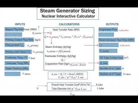
System Diagram

Steam Generator Sizing Calculator
How to Use This Calculator
- Select your calculation mode from the dropdown — choose from heat transfer area, thermal power, tube count, flow velocity, effectiveness, or pressure drop.
- Enter the required input values for your selected mode — temperatures, power, tube dimensions, flow rates, or fluid properties as prompted.
- Verify your units match the field labels (MW for power, °C for temperatures, mm for tube diameters, m for lengths).
- Click Calculate to see your result.
Nuclear Steam Generator Sizing Interactive Visualizer
Watch how thermal power, temperatures, and tube geometry drive the required heat transfer area in nuclear PWR steam generators. Adjust inputs to see real-time calculations of LMTD, effectiveness, and tube count for proper sizing.
HEAT TRANSFER AREA
3,817 m²
LMTD
27.3°C
TUBE COUNT
3,180
EFFECTIVENESS
0.67
FIRGELLI Automations — Interactive Engineering Calculators
Core Equations
Use the formula below to calculate required heat transfer area.
Heat Transfer Area Calculation
A = Q / (U × LMTD)
A = required heat transfer area (m²)
Q = thermal power transfer (W)
U = overall heat transfer coefficient (W/m²·K)
LMTD = log mean temperature difference (K)
Use the formula below to calculate the log mean temperature difference.
Log Mean Temperature Difference
LMTD = (ΔT1 - ΔT2) / ln(ΔT1 / ΔT2)
ΔT1 = temperature difference at hot end = Tprimary,in - Tsecondary (K)
ΔT2 = temperature difference at cold end = Tprimary,out - Tsecondary (K)
Use the formula below to calculate the number of tubes required.
Number of Tubes Required
N = A / (π × Do × L)
N = number of tubes (dimensionless)
Do = tube outer diameter (m)
L = active tube length (m)
Use the formula below to calculate flow velocity.
Flow Velocity
v = ṁ / (ρ × Aflow)
v = flow velocity (m/s)
ṁ = mass flow rate (kg/s)
ρ = fluid density (kg/m³)
Aflow = flow cross-sectional area (m²)
Use the formula below to calculate heat exchanger effectiveness.
Heat Exchanger Effectiveness
ε = Qactual / Qmax = Cmin(Th,in - Th,out) / [Cmin(Th,in - Tc,in)]
ε = effectiveness (dimensionless, 0 to 1)
Qactual = actual heat transfer rate (W)
Qmax = maximum possible heat transfer rate (W)
Cmin = minimum heat capacity rate (W/K)
Use the formula below to calculate pressure drop through the tubes.
Pressure Drop (Darcy-Weisbach)
ΔP = f × (L / D) × (ρv² / 2)
ΔP = pressure drop (Pa)
f = Darcy friction factor (dimensionless)
L = tube length (m)
D = tube inner diameter (m)
ρ = fluid density (kg/m³)
v = flow velocity (m/s)
Simple Example
Suppose a steam generator must transfer 500 MW of thermal power. Primary coolant enters at 320°C and exits at 290°C; secondary steam sits at 275°C. The overall heat transfer coefficient U is 4,800 W/m²·K.
- Hot end ΔT: 320 − 275 = 45°C
- Cold end ΔT: 290 − 275 = 15°C
- LMTD: (45 − 15) / ln(45/15) = 30 / 1.099 = 27.3°C
- Required area: 500 × 10⁶ / (4,800 × 27.3) = 3,817 m²
Theory & Engineering Applications
Nuclear Steam Generator Fundamentals
Nuclear steam generators in pressurized water reactors (PWRs) represent one of the most critical thermal-hydraulic interfaces in nuclear power generation. Unlike conventional fossil-fueled boilers that generate steam through direct combustion, PWR steam generators employ an indirect cycle where radioactive primary coolant transfers heat through thousands of thin-walled tubes to secondary feedwater, which boils to produce steam for the turbine cycle. This design philosophy maintains a robust barrier between the radioactive primary system and the secondary plant components, enabling safe power generation while containing fission products within the reactor coolant system.
The dominant steam generator design in modern PWRs is the vertical U-tube configuration, typically standing 20-22 meters tall with diameters of 4-5 meters and weighing 300-800 tonnes when fully assembled. These massive heat exchangers contain 3,000 to 16,000 inverted U-tubes with outer diameters ranging from 15.9 mm to 22.2 mm, most commonly 19.05 mm. Primary coolant enters through a single inlet nozzle at temperatures near 325°C and 15.5 MPa, flows upward through the tube bundle, and exits through a separate outlet nozzle after cooling to approximately 292°C. The secondary side operates at substantially lower pressure (typically 6-8 MPa) to produce saturated or slightly superheated steam at temperatures around 270-285°C.
Heat Transfer Coefficient Considerations
The overall heat transfer coefficient U in steam generators typically ranges from 3,500 to 6,000 W/m²·K, with most modern designs targeting 4,500-5,200 W/m²·K. This parameter critically depends on four thermal resistances in series: primary-side convection, tube wall conduction, fouling on both surfaces, and secondary-side boiling heat transfer. A non-obvious but critical consideration is that U degrades over the operating life of the steam generator due to fouling, corrosion product deposition, and tube plugging. Initial design calculations must incorporate a 15-25% fouling margin to ensure adequate performance at end-of-life conditions — this is a hard rule, not a suggestion.
Secondary-side fouling from impurities in the feedwater concentrates in the tube support plate crevices, leading to the industry-wide phenomenon of stress corrosion cracking and tube denting that has necessitated premature replacement of many steam generators at costs exceeding $400 million per unit. The tube material selection profoundly impacts both heat transfer and structural integrity. Early PWR steam generators used Inconel 600, a nickel-chromium alloy with excellent corrosion resistance but susceptibility to stress corrosion cracking in PWR environments. Modern replacement steam generators employ thermally-treated Inconel 690 or Alloy 800 Modified, which offer superior resistance to primary water stress corrosion cracking and intergranular attack. The tube wall thickness typically ranges from 1.07 mm to 1.27 mm, representing a compromise between maximizing heat transfer area (thinner walls increase thermal conductivity) and maintaining structural integrity to withstand pressure differentials and flow-induced vibration.
Thermal-Hydraulic Design Methodology
Steam generator sizing begins with the fundamental heat balance equation Q = UA × LMTD, but practical design requires sophisticated iterative analysis accounting for spatial variations in heat transfer coefficients, two-phase flow regimes on the secondary side, and structural constraints. The log mean temperature difference calculation assumes counterflow heat exchange, but actual U-tube steam generators exhibit complex mixed-flow patterns. The correction factor F adjusts the idealized LMTD for actual flow geometry, typically ranging from 0.92 to 0.97 for U-tube configurations. Lower F values indicate reduced thermal effectiveness and require proportionally larger heat transfer area to achieve the specified power output.
Secondary-side thermal-hydraulics involve complex boiling phenomena with distinct regions: subcooled boiling near the tube bundle bottom where feedwater first contacts hot tubes, nucleate boiling throughout most of the bundle height where vigorous vapor generation occurs, and steam-water separation in the upper regions. The circulation ratio (total secondary flow divided by steam production rate) typically ranges from 3 to 5 in recirculating steam generators, meaning that only 20-33% of the upward-flowing secondary water converts to steam in a single pass, with the remainder recirculating after separation. This high circulation ratio ensures adequate tube wetting and heat transfer but requires careful design of the steam-water separation equipment to minimize moisture carryover to the turbine, which would cause erosion and efficiency losses.
Structural and Mechanical Design Constraints
The tube bundle arrangement follows either square or triangular pitch patterns, with triangular pitch offering 15-20% greater packing density for a given shell diameter but complicating inspection access and tube plugging operations. Typical pitch-to-diameter ratios range from 1.25 to 1.40, balancing heat transfer enhancement (closer spacing increases secondary-side velocity and boiling heat transfer) against flow-induced vibration concerns and manufacturing feasibility. Tube support plates spaced at 0.5-0.7 meter intervals prevent destructive flow-induced vibration but create crevice regions prone to corrosion product accumulation and hideout chemistry effects during power transients.
Flow-induced vibration represents a perpetual engineering challenge in steam generator design. Primary-side flow velocities of 3.5-5.5 m/s and secondary-side cross-flow velocities can exceed 2 m/s in the tube bundle, creating vortex shedding, turbulent buffeting, and potentially fluidelastic instability. The critical velocity for fluidelastic instability scales with tube natural frequency, damping ratio, and mass ratio between fluid and tube. Modern steam generators incorporate anti-vibration bars in the U-bend region where tubes lack intermediate support and experience maximum flow velocities. Failure to properly address vibration led to catastrophic tube rupture events in the 1970s and 1980s, some resulting in forced plant shutdowns lasting months and regulatory interventions.
Worked Engineering Example: Steam Generator Area Calculation
Consider the design of a replacement steam generator for a Westinghouse 4-loop PWR operating at 3,411 MWt (thermal) reactor power. Each of four steam generators must transfer 852.75 MWt from the primary coolant to the secondary system. The design specifications are:
- Primary coolant inlet temperature: T₁,ᵢₙ = 326.7°C
- Primary coolant outlet temperature: T₁,ₒᵤₜ = 293.3°C
- Secondary steam temperature (saturated): T₂ = 279.4°C at 6.89 MPa
- Design overall heat transfer coefficient: U = 4,650 W/m²·K (accounting for 20% fouling margin)
- Tubes: Inconel 690 TT, OD = 19.05 mm, wall thickness = 1.09 mm
- Active tube length: L = 12.8 m (vertical height of straight sections plus U-bend equivalent)
Step 1: Calculate Log Mean Temperature Difference
The hot end temperature difference: ΔT₁ = T₁,ᵢₙ - T₂ = 326.7°C - 279.4°C = 47.3°C
The cold end temperature difference: ΔT₂ = T₁,ₒᵤₜ - T₂ = 293.3°C - 279.4°C = 13.9°C
LMTD = (ΔT₁ - ΔT₂) / ln(ΔT₁/ΔT₂) = (47.3 - 13.9) / ln(47.3/13.9) = 33.4 / ln(3.402) = 33.4 / 1.224 = 27.3°C
Step 2: Calculate Required Heat Transfer Area
Convert thermal power to watts: Q = 852.75 MWt × 10⁶ = 8.5275 × 10⁸ W
Assume correction factor F = 0.95 for U-tube geometry (verified iteratively with detailed thermal analysis)
Effective temperature difference: ΔT_eff = F × LMTD = 0.95 × 27.3°C = 25.9°C
Required area: A = Q / (U × ΔT_eff) = 8.5275 × 10⁸ / (4,650 × 25.9) = 8.5275 × 10⁸ / 120,435 = 7,082 m²
Step 3: Calculate Number of Tubes
Heat transfer area per tube: A_tube = π × D_o × L = π × 0.01905 m × 12.8 m = 0.766 m²
Number of tubes required: N = A / A_tube = 7,082 / 0.766 = 9,246 tubes
Round up to manufacturing standard: N = 9,260 tubes (accounting for 1-2% plugging margin)
Step 4: Verify Primary Side Flow Parameters
Primary coolant mass flow rate per steam generator: ṁ₁ = Q / (c_p × ΔT_primary)
Assuming c_p = 5,640 J/kg·K (average for pressurized water at 310°C): ṁ₁ = 8.5275 × 10⁸ / (5,640 × 33.4) = 4,527 kg/s
Tube inner diameter: D_i = 19.05 - 2(1.09) = 16.87 mm = 0.01687 m
Flow area per tube: A_flow = π × (0.01687)² / 4 = 2.235 × 10⁻⁴ m²
Total flow area: A_total = 9,260 × 2.235 × 10⁻⁴ = 2.070 m²
Primary coolant density at 310°C and 15.5 MPa: ρ₁ = 714 kg/m³
Average primary velocity: v₁ = ṁ₁ / (ρ₁ × A_total) = 4,527 / (714 × 2.070) = 3.06 m/s
This velocity falls within the optimal range of 2.8-3.5 m/s, providing adequate heat transfer without excessive pressure drop or erosion concerns.
Step 5: Calculate Actual Heat Transfer Area and Design Margin
Actual area provided: A_actual = 9,260 tubes × 0.766 m²/tube = 7,093 m²
Design margin: (A_actual - A_required) / A_required = (7,093 - 7,082) / 7,082 = 0.16% or 11 m²
This minimal margin indicates efficient design optimization. The 20% fouling factor already incorporated in the U value provides the necessary performance degradation allowance over the 40-year design life. Additional tubes can be plugged (up to 10% per Technical Specifications) if leaks develop, while maintaining adequate thermal performance at reduced power levels.
Industry Applications Across Nuclear Fleet
Steam generator sizing calculations apply across the global nuclear fleet of approximately 440 operating PWRs. Westinghouse designs dominate the U.S. market with 3-loop and 4-loop configurations, while Framatome (formerly Areva) supplies the French fleet of 58 reactors with standardized Model 51 and Model 68 steam generators. Russian VVER designs employ horizontal steam generators with different thermal-hydraulic characteristics but similar fundamental sizing principles. The Canadian CANDU design uses hundreds of small horizontal steam generators with fundamentally different geometry but identical heat transfer governing equations.
Beyond power generation, these calculations inform regulatory analysis for power uprates, steam generator replacements, and licensing basis reviews. The U.S. Nuclear Regulatory Commission requires detailed thermal-hydraulic analysis demonstrating adequate margin to departure from nucleate boiling (DNB) in the reactor core, which depends directly on steam generator heat removal capability. Modern probabilistic risk assessments model steam generator tube rupture as a design basis accident, requiring accurate heat transfer modeling to predict blowdown rates and radiological consequences. For more nuclear engineering calculations, visit the engineering calculator hub.
Practical Applications
Scenario: Replacement Steam Generator Design Evaluation
Jennifer, a lead mechanical engineer at a nuclear utility, is evaluating bids from vendors for replacement steam generators at her facility's 30-year-old PWR. The existing Model 44F steam generators show extensive tube degradation with 23% of tubes already plugged, reducing plant output by 4%. Vendor proposals specify different tube counts (8,750 vs 9,400 tubes), materials (Alloy 690 TT vs Alloy 800 Modified), and overall heat transfer coefficients (4,500 vs 4,850 W/m²·K). Using this calculator, Jennifer inputs each vendor's specifications along with her plant's operating parameters (primary inlet 326°C, outlet 292°C, secondary steam 278°C) to calculate the actual heat transfer area and thermal performance. The results show that Vendor A's design provides 7,240 m² with a 12% margin over minimum requirements, while Vendor B offers 7,890 m² with 23% margin but at $47 million higher cost. Jennifer's analysis demonstrates that Vendor A meets all Technical Specification requirements with adequate margin for 40-year operation, supporting her recommendation to plant management and ultimately saving the utility over $40 million while ensuring reliable performance through the plant's licensed life.
Scenario: Power Uprate Thermal Analysis
Marcus, a thermal-hydraulics engineer at a nuclear engineering consulting firm, is supporting a utility's application to the Nuclear Regulatory Commission for a 2% power uprate from 3,411 MWt to 3,479 MWt. The existing steam generators were designed with margin to accommodate this increase, but Marcus must demonstrate that adequate heat transfer capability exists at the uprated conditions. He uses this calculator to evaluate multiple operating scenarios: summer conditions with 32°C ultimate heat sink temperature requiring higher steam generator backpressure, winter conditions with 4°C cooling water enabling maximum turbine efficiency, and degraded conditions with 8% tube plugging. For each case, Marcus calculates the required heat transfer area, compares it to the installed area of 6,850 m² per steam generator, verifies that primary and secondary velocities remain within design limits, and confirms that tube wall temperatures stay below corrosion threshold values. His analysis reveals that even in the worst-case scenario (summer, end-of-cycle, maximum tube plugging), the steam generators retain 6.7% thermal margin above minimum requirements, providing the technical justification that convinces NRC reviewers to approve the uprate, generating an additional $18 million in annual revenue for the utility.
Scenario: Steam Generator Performance Monitoring and Diagnostics
Dr. Yuki Tanaka, a nuclear plant performance engineer, notices that Unit 2's "A" steam generator has been showing gradually declining heat transfer performance over the past three operating cycles. Plant instrumentation indicates that primary outlet temperature has increased from 292.8°C to 294.1°C while maintaining constant reactor power at 3,400 MWt, suggesting that the steam generator is not removing heat as effectively. Using this calculator in reverse mode, Dr. Tanaka inputs the measured operating temperatures, known tube geometry (9,150 tubes, 19.05 mm OD, 12.5 m length), and calculates backward to determine the effective overall heat transfer coefficient. The calculation yields U = 4,240 W/m²·K, compared to the design value of 4,750 W/m²·K and the predicted fouled value of 4,450 W/m²·K. This 9.6% degradation beyond expected fouling indicates abnormal deposits or tube degradation. Dr. Tanaka's analysis triggers an eddy current inspection during the next refueling outage, which discovers corrosion product buildup in the tube support plate crevices affecting 1,200 tubes. Chemical cleaning recovers most of the lost performance, and the calculator's diagnostic capability prevents what could have escalated to forced tube plugging and power reduction, saving the utility an estimated $12 million in replacement power costs.
Frequently Asked Questions
Why do PWR steam generators use U-tubes instead of straight-tube designs? +
How does fouling affect steam generator performance over its operating life? +
What is the significance of the log mean temperature difference in steam generator sizing? +
Why is tube pitch optimization important in steam generator design? +
How do operating conditions affect steam generator thermal performance? +
What role does steam generator sizing play in plant safety analysis? +
Free Engineering Calculators
Explore our complete library of free engineering and physics calculators.
Browse All Calculators →🔗 Explore More Free Engineering Calculators
About the Author
Robbie Dickson — Chief Engineer & Founder, FIRGELLI Automations
Robbie Dickson brings over two decades of engineering expertise to FIRGELLI Automations. With a distinguished career at Rolls-Royce, BMW, and Ford, he has deep expertise in mechanical systems, actuator technology, and precision engineering.
Need to implement these calculations?
Explore the precision-engineered motion control solutions used by top engineers.


