It’s not practical to wait years to see if a component fails, so most of us use accelerated life testing to get useful predictions faster. This calculator helps estimate field lifetime, test duration, acceleration factors, activation energy, and field failure rates. Plug in your test and use temperatures, along with activation energy, and you can work out the numbers you need. This method shows up a lot when you can’t do real-time qualification—think electronics, automotive parts, or medical devices—because deadlines and approval cycles are usually much shorter than actual field life. Below you’ll find the Arrhenius equations in use, a step-by-step example, details on the approach, and a FAQ that cuts through the common practical questions.
What is Accelerated Life Testing (Arrhenius)?
Accelerated life testing using the Arrhenius model is a method of predicting how long a product will last under normal conditions by running it at elevated temperatures for a shorter time. The temperature increase speeds up the same failure processes that would eventually occur in the field—compressing years of life into weeks of testing.
Simple Explanation
Think of it like baking: a cake bakes faster at a higher oven temperature, but it's still the same chemical process. Arrhenius testing works the same way—crank up the heat, watch the product degrade faster, then use the math to reverse-calculate how long it would have lasted at normal temperature. The key input is activation energy, which tells you how sensitive the failure mechanism is to temperature changes.
📐 Browse all 1000+ Interactive Calculators
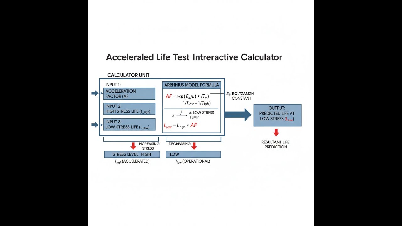
Arrhenius Relationship Diagram

Accelerated Life Test Arrhenius Calculator
How to Use This Calculator
- Select a calculation mode from the dropdown — choose what you want to solve for (field life, test time, acceleration factor, etc.).
- Enter the temperatures in °C — both the elevated test temperature and the normal use temperature.
- Enter the activation energy in eV — use a value from published data or from your own multi-temperature test results.
- Click Calculate to see your result.
This calculator is intended for education, concept evaluation, and preliminary design. Results are based on the equations and assumptions described on this page, but cannot account for every real-world load case, tolerance, material property, environmental condition, installation detail, safety factor, code, or regulatory requirement. Verify all inputs, assumptions, units, and results independently before selecting components or using the result in a real application. Safety-critical, structural, medical, lifting, transportation, or regulated applications must be reviewed by a qualified engineer.
Accelerated Life Test Arrhenius Interactive Calculator
Predict component field lifetime from elevated temperature testing using the Arrhenius relationship. Watch how temperature acceleration compresses years of life into weeks of testing.
ACCELERATION FACTOR
46.2×
FIELD LIFETIME
46,200 h
FIELD YEARS
5.3 years
FIRGELLI Automations — Interactive Engineering Calculators
Arrhenius Equations
Use the formula below to calculate the acceleration factor for Arrhenius accelerated life testing.
Acceleration Factor
AF = exp[Ea/k × (1/Tuse - 1/Tstress)]
AF = Acceleration factor (dimensionless)
Ea = Activation energy (eV, electron volts)
k = Boltzmann's constant (8.617333 × 10⁻⁵ eV/K)
Tuse = Use temperature (Kelvin)
Tstress = Test/stress temperature (Kelvin)
Field Life Prediction
Lfield = Ltest × AF
Lfield = Predicted field lifetime (hours)
Ltest = Measured test lifetime (hours)
Activation Energy from Two Tests
Ea = [ln(L2/L1) × k] / (1/T2 - 1/T1)
L1, L2 = Lifetimes at two different test temperatures (hours)
T1, T2 = Test temperatures (Kelvin)
Test Temperature for Desired Acceleration
Tstress = 1 / [(1/Tuse) - (ln(AF) × k / Ea)]
Used to determine the test temperature needed to achieve a specific acceleration factor
Failure Rate Translation
λfield = λtest / AF
λfield = Field failure rate (FIT, failures per billion hours)
λtest = Test failure rate (FIT)
MTBFfield = 1 / λfield (hours)
Simple Example
A component is tested for 1,000 hours at 85°C. Normal use temperature is 25°C. Activation energy is 0.7 eV.
- Ttest = 85°C = 358.15 K, Tuse = 25°C = 298.15 K
- AF = exp[(0.7 / 8.617×10-5) × (1/298.15 − 1/358.15)] ≈ 46.2×
- Predicted field life = 1,000 × 46.2 = 46,200 hours ≈ 5.3 years
Theory & Engineering Applications
The Arrhenius Relationship in Reliability Engineering
The Arrhenius equation, originally developed by Swedish chemist Svante Arrhenius in 1889 to describe the temperature dependence of chemical reaction rates, has become the cornerstone of accelerated life testing in modern reliability engineering. The fundamental premise is that many failure mechanisms—including diffusion, corrosion, oxidation, electromigration, and intermetallic growth—follow thermally activated processes where the reaction rate doubles approximately every 10°C increase in temperature. This relationship enables reliability engineers to compress decades of product life into weeks or months of testing by elevating temperature while maintaining the same failure mechanisms observed under normal operating conditions.
The acceleration factor quantifies this time compression. For a typical activation energy of 0.7 eV (common for silicon-based semiconductors), testing at 85°C instead of 25°C yields an acceleration factor of approximately 46×, meaning that 1,000 hours of testing at 85°C represents approximately 46,000 hours (5.25 years) of field operation at 25°C. This dramatic compression makes it economically feasible to validate product reliability claims during development cycles that would otherwise be impossible. However, the validity of this extrapolation hinges critically on maintaining the same failure mechanisms at both temperatures—a condition that requires careful validation and is one of the most significant limitations of Arrhenius-based testing.
Activation Energy: The Physical Foundation
Activation energy (Ea) represents the minimum energy barrier that must be overcome for a failure-inducing reaction to proceed. In semiconductor devices, typical values range from 0.3 eV for some surface phenomena to 1.2 eV for bulk diffusion processes. Electromigration in aluminum interconnects typically exhibits Ea = 0.5-0.7 eV, while solder joint intermetallic formation ranges from 0.8-1.1 eV depending on alloy composition. These values are not universal constants but depend on material systems, manufacturing processes, and environmental conditions.
A critical but often overlooked consideration is that activation energy is not always constant across the entire temperature range. Many systems exhibit "knee points" where the dominant failure mechanism changes, invalidating simple Arrhenius extrapolation. For instance, moisture-related failures may dominate below 60°C, while purely thermal degradation dominates above 100°C. This mechanism transition can produce misleading results if not recognized. Reliability engineers must validate that the same failure modes and mechanisms observed in accelerated tests also occur in the field—typically accomplished through failure analysis, distribution function comparison, and physics-of-failure verification.
Determining Activation Energy from Experimental Data
While theoretical activation energies exist for pure materials and simple processes, real-world products require empirical determination through multi-temperature testing. The most rigorous approach involves testing identical samples at three or more temperatures, plotting ln(lifetime) versus 1/T (Kelvin), and extracting Ea from the slope. The linearity of this Arrhenius plot serves as validation that a single thermally activated mechanism dominates across the tested range.
For products with multiple potential failure mechanisms, the observed activation energy may represent a composite value. Ceramic capacitors, for example, can fail through dielectric breakdown (Ea ≈ 1.0 eV), termination adhesion degradation (Ea ≈ 0.6 eV), or electrode migration (Ea ≈ 0.8 eV). The measured activation energy will reflect whichever mechanism occurs first under the test conditions, which may not be the dominant field failure mode. This highlights the importance of comprehensive failure analysis alongside accelerated testing—statistical predictions alone are insufficient for robust reliability engineering.
Practical Limitations and Test Design Considerations
The maximum practical test temperature is constrained by several factors. First, the test must not induce failure mechanisms that would never occur under normal use—testing plastic-encapsulated devices above their glass transition temperature, for instance, introduces package-related failures irrelevant to field performance. Second, many standards recommend limiting the test temperature to where the Arrhenius relationship remains valid, typically 0.8× the absolute melting temperature for metallurgical processes or below polymer degradation temperatures for organic materials.
Industry practice generally limits acceleration factors to 50-100× to maintain mechanism validity. While the mathematics permits higher acceleration (testing at 150°C might yield AF = 500×), such extreme conditions rarely produce field-relevant data. The relationship between test severity and data quality is non-linear: doubling the temperature may reduce test time by 90% but can compromise result validity if mechanism transitions occur.
Comprehensive Worked Example: MOSFET Reliability Qualification
Consider a power MOSFET manufacturer qualifying a new device family for automotive applications. The specification requires demonstrating 15-year lifetime at 105°C junction temperature with less than 10% parametric drift. Direct testing would require over 131,000 hours—economically and schedule-wise infeasible. Instead, the reliability engineer designs an accelerated life test using the Arrhenius model.
Step 1: Establish Activation Energy
Previous qualification data for similar device structures showed gate oxide degradation (the dominant failure mechanism) has Ea = 0.85 eV. To validate this for the new design, preliminary tests run 30 devices at 155°C and 30 devices at 175°C for 500 hours each. At 155°C, median time to 5% threshold voltage shift is 2,847 hours. At 175°C, it's 823 hours.
Calculate actual activation energy:
- T1 = 155°C = 428.15 K
- T2 = 175°C = 448.15 K
- L1 = 2,847 hours
- L2 = 823 hours
- k = 8.617333 × 10⁻⁵ eV/K
Ea = [ln(2847/823) × 8.617333 × 10-5] / [(1/448.15) - (1/428.15)]
Ea = [ln(3.4594) × 8.617333 × 10-5] / [0.002232 - 0.002335]
Ea = [1.2414 × 8.617333 × 10-5] / [-0.000103]
Ea = 0.000107 / 0.000103 = 1.039 eV
The measured value (1.039 eV) differs from the historical 0.85 eV, likely due to improved gate oxide processing. The engineer proceeds with Ea = 1.039 eV, which is conservative (higher Ea means lower acceleration, requiring longer test time).
Step 2: Calculate Required Test Conditions
Target field life: 15 years at 105°C = 131,400 hours
Desired test duration: 2,000 hours (practical for production qualification schedule)
Required acceleration factor: 131,400 / 2,000 = 65.7×
Calculate required test temperature:
Tuse = 105°C = 378.15 K
AF = 65.7
Ea = 1.039 eV
Tstress = 1 / [(1/378.15) - (ln(65.7) × 8.617333 × 10-5 / 1.039)]
Tstress = 1 / [0.002645 - (4.185 × 8.617333 × 10-5 / 1.039)]
Tstress = 1 / [0.002645 - (0.000361 / 1.039)]
Tstress = 1 / [0.002645 - 0.000347]
Tstress = 1 / 0.002298 = 435.16 K = 162°C
Step 3: Validate and Execute Test
Testing at 162°C provides the required 65.7× acceleration. The reliability engineer runs 100 devices for 2,000 hours at 162°C junction temperature with continuous electrical bias. Three devices exceed the 5% threshold voltage shift criterion at 1,847, 1,923, and 2,106 hours respectively. This yields a test failure rate of 3 failures / (100 units × 2,000 hours) = 1.5 × 10⁻⁵ failures/hour = 15,000 FIT.
The field failure rate prediction:
λfield = λtest / AF = 15,000 FIT / 65.7 = 228 FIT
MTBFfield = 109 / 228 = 4.39 × 10⁶ hours = 501 years
This exceeds the 15-year requirement by over 30×, providing substantial margin. The product passes qualification. Notably, if the engineer had used the historical Ea = 0.85 eV instead of the measured 1.039 eV, the calculated acceleration factor would have been only 28.3×, yielding a non-conservative field prediction of 530 FIT—a 2.3× overestimate of failure rate that could lead to field reliability issues.
Advanced Applications and Multi-Stress Testing
While single-variable temperature acceleration is the most common application, modern reliability engineering frequently combines thermal stress with voltage, humidity, or mechanical stress using multi-variable acceleration models. The temperature-humidity-bias (THB) test, for instance, combines Arrhenius thermal acceleration with Peck's humidity model and voltage acceleration to simulate corrosive environments. Such combined models can achieve acceleration factors exceeding 1000×, though with correspondingly increased uncertainty regarding mechanism fidelity.
For systems with multiple independent failure modes, reliability engineers must conduct mode-specific testing or use competing risk analysis. An automotive ECU might experience solder joint fatigue (thermal cycling), connector corrosion (humidity + temperature), and semiconductor degradation (temperature + voltage)—each with different activation energies and acceleration relationships. Comprehensive qualification requires addressing each mechanism independently, then combining the results using probability theory to predict overall system reliability.
For additional reliability calculations including thermal cycling, humidity acceleration, and system-level MTBF predictions, explore the complete collection at the FIRGELLI engineering calculator library, which includes tools for mechanical stress analysis, fatigue life prediction, and statistical reliability modeling.
Practical Applications
Scenario: Medical Device Regulatory Submission
Dr. Jennifer Chen, a reliability engineer at a medical device startup, faces a critical deadline. The FDA requires demonstration that their implantable glucose sensor will function reliably for 180 days at body temperature (37°C) before they can begin clinical trials. Testing 100 sensors for six months would delay the program by half a year and consume $500,000 in resources. Instead, Jennifer uses Arrhenius acceleration with the manufacturer's published Ea = 0.92 eV for the polymer membrane degradation mechanism. Testing at 67°C provides an acceleration factor of 32.4×, meaning just 133 hours (5.5 days) of elevated temperature testing represents the full 180-day requirement. By running 150 sensors at 67°C for 200 hours with only one failure, she demonstrates a predicted field MTBF of 4,200 days—well exceeding the 180-day specification with statistical confidence. This accelerated approach saved five months of development time and enabled the team to meet their regulatory submission deadline.
Scenario: LED Lighting Warranty Determination
Marcus Torres, quality director for an LED lighting manufacturer, needs to determine what warranty period the company can confidently offer on their new industrial high-bay luminaire operating at 65°C LED junction temperature. Rather than wait years for field data, Marcus conducts a three-temperature Arrhenius study at 95°C, 115°C, and 135°C, measuring time to 30% lumen depreciation (L70). The resulting Arrhenius plot yields Ea = 1.18 eV with excellent linearity (R² = 0.987), confirming a single dominant degradation mechanism across the range. Using the calculator with test data showing 8,500 hours median life at 95°C, Marcus predicts 73,400 hours (8.4 years) of L70 life at the 65°C operating temperature. With this data, the company confidently offers a 50,000-hour (5.7 year) warranty—industry-leading for this luminaire class—while maintaining a 1.47× safety margin. The Arrhenius-based prediction proves accurate: after 18 months in the field, early returns show measured degradation rates within 12% of predicted values, validating the accelerated test methodology.
Scenario: Aerospace Component Qualification
Sarah Kim, an aerospace reliability engineer, must qualify a new flight control actuator for a satellite with a 15-year mission life at -20°C to +70°C operational range. The worst-case thermal environment analysis shows critical electronics spending 60% of orbital time at 45°C. Testing for 15 years is impossible, but Sarah cannot use extreme acceleration—aerospace standards limit test temperature to 105°C maximum to avoid non-representative failure modes in space-qualified components. Using measured Ea = 0.68 eV from preliminary multi-temperature testing, she calculates that 105°C testing provides only 18.2× acceleration relative to 45°C operation. To demonstrate 15 years (131,400 hours) requires 7,220 hours (301 days) of testing—almost ten months. Sarah designs a test with 25 actuators running 8,000 hours at 105°C under worst-case electrical and mechanical loading. When all 25 units complete without failure, this demonstrates greater than 2.63 million device-hours at use conditions with zero failures, providing the statistical confidence required for mission-critical aerospace qualification. The extended test duration, though lengthy compared to commercial electronics, remains practical compared to real-time mission duration testing.
Frequently Asked Questions
What is a typical activation energy value, and how do I find it for my product? +
How high can I safely set my test temperature to maximize acceleration? +
Can I use Arrhenius acceleration for mechanical failures like solder fatigue? +
What sample size do I need for statistically valid accelerated life testing? +
How do I handle products with multiple failure mechanisms with different activation energies? +
What's the difference between Arrhenius and Eyring models, and when should I use each? +
Free Engineering Calculators
Explore our complete library of free engineering and physics calculators.
Browse All Calculators →🔗 Explore More Free Engineering Calculators
About the Author
Robbie Dickson — Chief Engineer & Founder, FIRGELLI Automations
Robbie Dickson brings over two decades of engineering expertise to FIRGELLI Automations. With a distinguished career at Rolls-Royce, BMW, and Ford, he has deep expertise in mechanical systems, actuator technology, and precision engineering.
Video Walkthrough - How to Use This Calculator
Need to implement these calculations?
Explore the precision-engineered motion control solutions used by top engineers.


