When you’re working with antenna design, optical fiber, or spectroscopy gear, the relationship between wavelength, frequency, and wave speed isn’t just textbook—get it wrong and your design won’t work. This Wavelength to Frequency Calculator figures out frequency, wavelength, period, photon energy, angular frequency, and wavenumber based on whichever input you’ve got. You select your propagation medium because it makes a difference—especially outside of vacuum. These conversions show up everywhere: RF circuits, fiber systems, photonics labs. If you mess up a unit or forget to account for material velocity, you get the wrong antenna length or bandwidth. The rest of this page covers real equations, example calculations for practical cases, material effects on wave speed, dispersion, and what trips engineers up most often.
What is wavelength-to-frequency conversion?
This is simply connecting how the number of wave cycles per second (frequency) relates to the length of each cycle (wavelength), using wave speed as the link. Divide velocity by wavelength, you get frequency. That’s all there is to it, but don’t ignore units or material differences, or you’ll get the answer wrong.
Simple Explanation
If you picture waves on a pond, wavelength is the distance from crest to crest. Frequency is just how many crests go by in a second. Speed up the ripples or make them closer together, and more pass per second. That’s the direct relationship this calculator uses. The math is the same regardless of whether it’s water waves, radio, or light—you just change the wave speed for the right medium.
📐 Browse all 1000+ Interactive Calculators
How to Use This Calculator
- Select your calculation mode from the dropdown — choose from Wavelength → Frequency, Frequency → Wavelength, Photon Energy → Frequency, and more.
- Enter your known value in the input field that appears and select the appropriate unit from the unit dropdown.
- Select the propagation medium (vacuum, water, glass, diamond, or a custom velocity).
- Click Calculate to see your result.
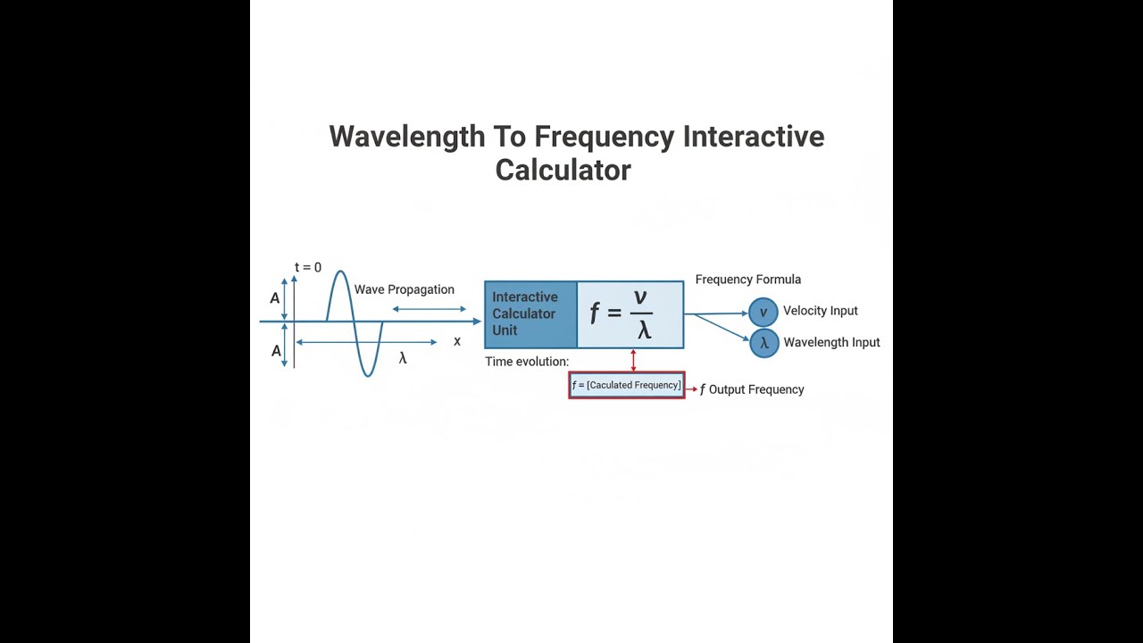
Wave Propagation Diagram

Wavelength-Frequency Calculator
This calculator is intended for education, concept evaluation, and preliminary design. Results are based on the equations and assumptions described on this page, but cannot account for every real-world load case, tolerance, material property, environmental condition, installation detail, safety factor, code, or regulatory requirement. Verify all inputs, assumptions, units, and results independently before selecting components or using the result in a real application. Safety-critical, structural, medical, lifting, transportation, or regulated applications must be reviewed by a qualified engineer.
Wavelength to Frequency Interactive Visualizer
Instantly see how the relationship c = λf plays out across the electromagnetic spectrum. Change wavelength or frequency and you’ll get updated conversions, including energy, and watch the corresponding wave animation.
FREQUENCY
600 THz
PERIOD
1.67 fs
PHOTON ENERGY
2.48 eV
FIRGELLI Automations — Interactive Engineering Calculators
Fundamental Wave Equations
For these calculations you’ll be using the following basic formulas to move between frequency, wavelength, and other properties:
Primary Wave Relationship
c = λf
f = c / λ
λ = c / f
Related Wave Parameters
Period: T = 1 / f
Angular Frequency: ω = 2πf
Wavenumber: k = 2π / λ
Photon Energy: E = hf = hc / λ
Variable Definitions:
- c = wave velocity (m/s) — speed of light in vacuum = 2.998 × 10⁸ m/s
- λ = wavelength (m) — spatial period of the wave
- f = frequency (Hz) — number of oscillations per second
- T = period (s) — time for one complete oscillation
- ω = angular frequency (rad/s) — rate of phase change
- k = wavenumber (rad/m) — spatial frequency
- E = photon energy (J) — quantum energy of electromagnetic radiation
- h = Planck's constant = 6.626 × 10⁻³⁴ J·s
Simple Example
Green light’s typical wavelength is 500 nm. In vacuum, c = 2.998 × 10⁸ m/s.
Convert 500 nm to meters: 500 nm = 500 × 10−9 m = 5 × 10⁻⁷ m
Then: f = c / λ = 2.998 × 10⁸ / 5 × 10−7 = 5.996 × 10¹⁴ Hz ≈ 599.6 THz
This puts you in the visible portion of the spectrum.
Wave Theory & Practical Applications
Fundamental Wave-Particle Duality in Electromagnetic Radiation
For electromagnetic waves, the wavelength-frequency equation c = λf is always true in vacuum no matter what. The speed of light (299,792,458 m/s) doesn’t depend on wavelength—only the medium changes that value. This is unlike mechanical waves, where speed is set by the material. In vacuum, everything from radio waves to gamma rays rides along at the same speed.
Once you’re in a material—like glass or fiber—the situation shifts. Now, velocity depends on refractive index, and because refractive index depends on frequency, your wave speed and therefore your wavelength change, even though frequency stays fixed (it’s determined at the source). This is called dispersion and it bites hard in fiber optics. For example, over 100 km, green and red light pulses spread apart in silica fiber and limit your maximum data rate. Engineers use the dispersion parameter D (ps/(nm·km)) to work out just how much a pulse will broaden, setting a cap on how many bits per second a link can really handle without resorting to compensation techniques.
Electromagnetic Spectrum Applications Across Industries
This calculation isn’t just a science exercise—it’s a tool used across everything from antennas to spectrometers. In RF, antenna sizes are based on wavelength, not frequency. You’ll see real numbers: A 1.9 GHz base station needs a λ/4 monopole of 39.45 mm in free space, but after you account for construction details and velocity factor (0.95 for typical metals), your actual length comes out shorter—about 38.5 mm. The wavelength-to-frequency equation is what drives those dimension choices.
In optics, choosing the right operating window comes down to specific losses and dispersion for each wavelength. The 1550 nm window in fiber is popular because it’s got minimum attenuation, but frequency spacing for DWDM channels only makes sense after you convert all those wavelengths to actual carrier frequencies. Channel spacing and avoiding crosstalk don’t work if you get this wrong.
Spectrometers and elemental analysis often start with known photon energies or precisely measured wavelengths. Converting those to energy using E = hc/λ is how you set up the experiment and calibrate for different elements. For example, the copper Kα line (8.048 keV) equates to 0.15406 nm—without careful conversion, your X-ray optics or detectors will miss their mark.
Refractive Index Effects and Group Velocity Considerations
Real materials rarely have a constant refractive index across all wavelengths. The speed you calculate (phase velocity) isn’t always the same as the speed at which a modulated signal or light pulse travels (group velocity). For most glass, the group velocity is a little slower than what you’d estimate from the usual n—sometimes by half a percent or more. If you’re sending femtosecond pulses through fiber or glass, dispersion spreads the pulse by an amount set by the wavelength dependence of refractive index. Once you get into ultrafast optics or precise timing, you have to use group velocities and account for the second derivative of n versus λ.
Worked Example: Multi-Band Communication System Design
Problem: You’re building a dual-band WiFi system in a building with concrete walls (εr = 6.0), operating at 2.437 GHz and 5.180 GHz. Work out the right antenna sizes for both bands, and see how the wavelength affects wall penetration loss, given α ≈ 0.4f0.5 dB/m (f in GHz).
Solution Part 1 - Free Space Wavelengths:
2.4 GHz: λ = c / f = (2.998 × 10⁸) / (2.437 × 10⁹) = 0.123 m = 123 mm
Quarter-wave monopole: L = λ/4 = 30.75 mm (apply velocity factor 0.95: length = 29.2 mm)
5.2 GHz: λ = c / f = (2.998 × 10⁸) / (5.180 × 10⁹) = 0.0579 m = 57.88 mm
Quarter-wave monopole: L = λ/4 = 14.47 mm (14.47 × 0.95 = 13.7 mm actual)
Solution Part 2 - Wavelength in Concrete:
The new wavelength is λ₀ divided by √εr:
2.4 GHz: 123 mm / √6 = 50.2 mm
5.2 GHz: 57.88 mm / √6 = 23.6 mm
Solution Part 3 - Penetration Loss Through 200mm Wall:
2.4 GHz: α = 0.4 × (2.437)^0.5 = 0.624 dB/m → for 0.2 m: 0.624 × 0.2 = 0.125 dB
5.2 GHz: α = 0.4 × (5.180)^0.5 = 0.910 dB/m → for 0.2 m: 0.910 × 0.2 = 0.182 dB
So 5.2 GHz suffers about 1.46× the loss per wall as 2.4 GHz.
Solution Part 4 - Link Budget Impact:
With receiver sensitivity at -70 dBm and transmit power at +20 dBm, path loss can be up to 90 dB. With each wall, 5.2 GHz loses an extra 0.055 dB relative to 2.4 GHz. Go through five walls, total difference is 0.28 dB. At this scale, that doesn’t end a link but starts to reduce range—here, by about 6%, and that’s just from this wall loss difference. Shorter wavelength at higher frequency also means poorer diffraction around corners, which matters for indoor coverage planning.
Quantum Photonics and Energy-Wavelength Precision
Photon energy and wavelength are linked tightly if you’re in quantum or optical communication work. For entangled photon pairs or single-photon sources, small changes in λ show up as mismatches in coherence time or interference. Temperature and wavelength have a tight relationship in many nonlinear crystals, so if you need a certain channel within ±0.1 nm, you’ll often be adjusting crystal temperature by less than 2°C at a time to keep things stable—a practical detail you’ll run into in the lab.
RF Spectrum Allocation and Regulatory Compliance
Spectrum is allocated in frequency bands, but the hardware—especially antennas—depends on wavelength. For example, the 5G n77 band (3.3–4.2 GHz) needs you to check both edge and center frequencies to nail down spacing for MIMO arrays. If you don’t adjust for wavelength at the actual frequency you’re using (not just the band center), your phased array will throw beams a few degrees off target at the edges of the band, especially in systems with wide instantaneous bandwidths. This is often called beam squint and can’t be ignored in 5G base stations or anything using software beam forming.
Frequently Asked Questions
Free Engineering Calculators
Explore our complete library of free engineering and physics calculators.
Browse All Calculators →🔗 Explore More Free Engineering Calculators
About the Author
Robbie Dickson — Chief Engineer & Founder, FIRGELLI Automations
Robbie Dickson brings over two decades of engineering expertise to FIRGELLI Automations. With a distinguished career at Rolls-Royce, BMW, and Ford, he has deep expertise in mechanical systems, actuator technology, and precision engineering.
Video Walkthrough - How to Use This Calculator
Need to implement these calculations?
Explore the precision-engineered motion control solutions used by top engineers.


