Managing reactor core temperature comes down to moving a huge amount of heat away from the fuel — hundreds or thousands of megawatts — and keeping the flow in a workable range. If you get this wrong, it's not a small mistake. The tool here helps with the main calculations: how much coolant you need to move, how much heat you can take away for a given flow, resulting temperature difference, pump power, coolant speed, and Reynolds number. The calculator is set up for the main reactor types — PWRs, BWRs, and SMR core cooling — and should be a practical reference for both initial scoping and quick checks. Everything is based on direct input values (thermal power, flow, temperature, pressure, geometry, etc.) rather than idealized numbers to keep the focus on engineering reality. Equations, a step-by-step example, and plain discussion of the theory are all included further down with no sales pitch.
What is reactor coolant flow?
Coolant flow in a reactor is just the ongoing movement of fluid through the core to take heat away at the right rate. Most systems use pressurized water. The flow has to be high enough to keep every part of the fuel cool enough, even in abnormal operating states. Details like turbulence and channel geometry do matter, but you set your baseline with mass flow and temperature rise that keep maximum fuel temperatures inside limits.
Simple Explanation
If you imagine a reactor core as a giant, overpowered stove element and the coolant as the stream of water over it, the job is really to keep that water flowing fast enough that it doesn’t get dangerously hot. Big plants use pumps to move huge quantities of water — tens of thousands of kilograms every second — through the fuel. If you undershoot the flow, the fuel temperature spikes; overshoot too much, and you waste enormous energy and cause excessive erosion. So, you’re always looking for a balance — “just enough, but not too much.”
📐 Browse all 1000+ Interactive Calculators
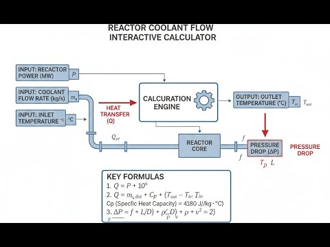
Reactor Coolant Flow System Diagram

Reactor Coolant Flow Calculator
How to Use This Calculator
This calculator is intended for education, concept evaluation, and preliminary design. Results are based on the equations and assumptions described on this page, but cannot account for every real-world load case, tolerance, material property, environmental condition, installation detail, safety factor, code, or regulatory requirement. Verify all inputs, assumptions, units, and results independently before selecting components or using the result in a real application. Safety-critical, structural, medical, lifting, transportation, or regulated applications must be reviewed by a qualified engineer.
- Pick the calculation type you want (mass flow, heat removal, temperature rise, etc.).
- Type in the numbers as prompted. The relevant fields (power, flow, temp rise, efficiency, area, properties, etc.) change as you change the mode.
- If you want a real plant example, use the Try Example button.
- When the numbers are set, hit Calculate and read your result directly below.
Reactor Coolant Flow Interactive Visualizer
You can see directly how changes in thermal power, flow rate, and temperature rise affect each other in keeping the reactor core cool. Try adjusting the values to get a quick sense of the tradeoffs between cooling capacity and what you actually have to build into the system.
TEMP RISE
32.1°C
VELOCITY
4.3 m/s
REYNOLDS
2.4×10⁵
FIRGELLI Automations — Interactive Engineering Calculators
Governing Equations
Simple Example
A reactor produces 1000 MW thermal. The coolant has a specific heat of 5.0 kJ/kg·K and the allowed temperature rise across the core is 40°C.
ṁ = (1000 × 1000) / (5.0 × 40) = 5,000 kg/s required mass flow rate.
If coolant density is 700 kg/m³ and flow area is 2.0 m², coolant velocity = 5000 / (700 × 2.0) = 3.57 m/s.
Heat Balance Equation
Use the formula below to calculate reactor heat removal.
Q = ṁ · cp · ΔT
Where:
- Q = Thermal power removed (MW or kW)
- ṁ = Mass flow rate of coolant (kg/s)
- cp = Specific heat capacity at constant pressure (kJ/kg·K)
- ΔT = Temperature rise across reactor core (°C or K)
Mass Flow Rate Calculation
Use the formula below to calculate required coolant mass flow rate.
ṁ = Q / (cp · ΔT)
This fundamental relationship determines the required coolant circulation rate to remove a specified thermal power given the allowable temperature rise and coolant properties.
Coolant Velocity
Use the formula below to calculate coolant velocity from mass flow rate, density, and flow area.
v = ṁ / (ρ · A)
Where:
- v = Average coolant velocity (m/s)
- ρ = Coolant density (kg/m³)
- A = Flow cross-sectional area (m²)
Pump Power Requirement
Use the formula below to calculate required reactor coolant pump shaft power.
Pshaft = (Qvol · Δp) / ηpump
Where:
- Pshaft = Required shaft power (kW or MW)
- Qvol = Volumetric flow rate (m³/s) = ṁ / ρ
- Δp = System pressure drop (kPa or MPa)
- ηpump = Pump efficiency (decimal fraction)
Reynolds Number
Use the formula below to calculate Reynolds number and determine flow regime in reactor coolant channels.
Re = (ρ · v · Dh) / μ
Where:
- Re = Reynolds number (dimensionless)
- Dh = Hydraulic diameter (m)
- μ = Dynamic viscosity (Pa·s or kg/m·s)
Reynolds number determines flow regime and influences heat transfer correlations and pressure drop calculations in reactor thermal-hydraulic analysis.
Theory & Engineering Applications
Reactor coolant flow is at the core of nuclear plant safety. Its main job is straightforward: get the fission heat out, and (sometimes) help with neutron moderation. In a PWR, the numbers are big: 15.5 MPa, entering at about 290°C and coming out at 325°C. The design calculations need to guarantee that cooling always keeps up, not just at normal full power, but also when things go off-normal — like pump trips, shutdowns, or accident conditions. If the analysis is weak here, nothing else in the plant can make up for it.
Fundamental Heat Transfer Mechanisms in Reactor Cores
The heat isn’t spread evenly in a reactor core. There are “hot channels” due to peaking, meaning some assemblies are always running hotter than average by 30-60%. This unevenness sets the true minimum flow you need, since you size coolant flow to the worst-case (not average) point. If the flow drops too much, the margin to departure from nucleate boiling (DNBR) shrinks fast — and if you lose nucleate boiling, surface film boiling takes over, heat transfer collapses, and the fuel overheats rapidly. For turbulent flow in rod bundles, the heat transfer coefficient depends strongly on velocity and somewhat on hydraulic diameter. A drop in flow might look small, but it takes a big chunk out of your safety margin because so much is nonlinear.
This nonlinearity is crucial: drop flow by 20% and you might lose almost as much margin on heat transfer coefficient, risking a trip into film boiling. That's why everyone with reactor cooling experience designs with a healthy safety buffer and is conservative in their numbers.
Coolant Property Variations and System Design
In a nuclear plant, coolant properties actually change a fair bit over the loop. Density drops from inlet to outlet. The specific heat goes up on the hot side. Both density and specific heat swings need to be accounted for if you want calculations to match reality — otherwise, temperature and flow distribution won’t stay where you expect. Dynamic viscosity drops as temperature rises, which directly bumps your Reynolds number and changes your pressure drop. For anything beyond a rough sizing, don't just pick one value for density/viscosity/specific heat. Work with tables, or at least take values at characteristic “hot” and “cold” points if you can't integrate across the whole range.
Primary Coolant Pump Engineering
Pumps in nuclear applications are not your standard industrial units. For large PWRs, each pump delivers up to 8 MW shaft power to keep 20,000 kg/s flowing through a loop. The physical design is chunky and specialized. There are large flywheels for coastdown, strict sealing arrangements for no leakage, and robust support for seismic events. High-inertia means after a power cut, the pump still coast downs long enough for emergency cooling systems to start — not just a comfort, but a licensing requirement. The vertical motor helps with space and maintenance, but is also there to keep primary coolant where it belongs, not on the floor.
Most of the required pump power comes from brute force: flow (m³/s) times overall system pressure drop. For a large PWR, expect total primary side pressure drops in the range of 350-450 kPa, of which the core is often a third or less. The rest is lost across steam generators, pipes, bends, valves, and minor losses that add up. Pump efficiency isn’t perfect (low to mid 80s percent for big vertical machines), and all inefficiency becomes waste heat dumped back into the system, so that too has to be balanced in the overall heat calculations. You can't overlook a 15-20 MW thermal load if you want tight temperature control.
Worked Example: PWR Primary System Design
Let’s walk through a real-world example. Assume you’re sizing the coolant system for a 3400 MWth PWR with four loops. Entry temperature: 292.8°C. Exit: 326.7°C. Pressure: 15.51 MPa. Specific heat averaged over the range: 5.82 kJ/kg·K.
Step 1: Calculate total required mass flow rate
Mass flow needed is Q / (cp × ΔT): 3400 MW / (5.82 × (326.7 - 292.8)). You get roughly 17,232 kg/s total.
Step 2: Determine flow per loop
Divide by four: about 4,308 kg/s per loop.
Step 3: Calculate volumetric flow rate
With density at mean temp (715 kg/m³): 4,308 / 715 ≈ 6.03 m³/s for each loop.
Step 4: Determine coolant velocity in reactor vessel
Assume vessel downcomer area is 3.85 m²: 6.03 m³/s / 3.85 m² = 1.57 m/s.
Step 5: Calculate core flow velocity
Account for real core flow area (say 4.92 m² with blockages): 6.03 / 4.92 ≈ 1.23 m/s on average. The hottest subchannels will be higher, maybe 1.35-1.4 m/s due to local redistribution.
Step 6: Determine pump power requirement
Let’s say 385 kPa total loss per loop, pump efficiency 85%: 6.03 m³/s × 385 kPa = 2,320 kW hydraulic; at the shaft, you’ll need 2,729 kW. With a 96% efficient motor, electrical draw is about 2,843 kW per pump.
Step 7: Verify Reynolds number for turbulent flow
Try 0.0117 m channel diameter, viscosity 8.4×10⁻⁵ Pa·s: Re = (715 × 1.23 × 0.0117) / 8.4e-5 ≈ 122,000. That’s well into the fully turbulent range (laminar-turbulent transition is at Re ≈ 2300-4000 depending on channel geometry).
Step 8: Calculate heat addition to coolant from pump work
Pumping losses get dumped back into the coolant: (1 - 0.85) × 2,729 kW = 409 kW per pump, so 1.6 MW total for four — not huge compared to the core power, but not zero.
Advanced Considerations in Modern Reactor Design
For SMRs, the design quirks are different. Some move the steam generators inside the pressure vessel, cutting primary loop size but making flow control, distribution, and pump layout trickier. Canned-motor pumps (motors in the coolant itself) avoid shaft seals but now the motor heat must be removed by the coolant, and you need to be sure it doesn’t trip any margins. Fully natural circulation means no pumps at all, but piping diameter and elevation difference have to be sized up to allow the density differences to move enough coolant passively. For all these options, the same fundamentals apply: you work power, flow, and temperature (Q = ṁ·cp·ΔT) against real geometry and property variations — now with a few extra moving parts to factor in.
If you want engineering tools for calculations in this field, see the FIRGELLI engineering calculator library. It covers physics, heat transfer, fluids, and more, including direct-use calculators for plant and system sizing.
Practical Applications
Scenario: Refueling Outage Flow Verification
At a three-loop PWR, the plant is coming back up from a refueling outage. A main coolant pump got replaced. Before restart, engineering needs to show the replacement delivers the 23,476 kg/s mass flow at the design point. Plug in real values: 3,565 MW rated power, inlet at 291.4°C, outlet at 325.8°C, water at 5.78 kJ/kg·K. The direct calculation confirms the target flow and provides volumetric flow for verification checks. With a measured loop pressure drop of 394 kPa and pump efficiency at 84.3%, the calculator confirms the new motor rating of 7,240 kW is enough. These are the kinds of numbers a real sign-off is based on — not just theory, but checks against actual plant constraints, before anyone considers approaching criticality.
Scenario: Small Modular Reactor Core Design
For a 300 MWth SMR with an integral core and compact internal steam generators, velocity management is key to prevent vibration and keep cooling reliable. Working out 2,847 kg/s total flow through a 1.83 m² area (density 695 kg/m³) gives 2.18 m/s average — higher than big PWRs, but expected for smaller, denser layouts. Calculate Re next: with velocity at 2.18 m/s, subchannel diameter 0.0094 m, and viscosity 7.9×10⁻⁵ Pa·s, you see ≈191,300 — still comfortably turbulent for heat transfer models. These checks are what let you show the design is actually workable, not just on a slide but in physical operation with safety margins and technical specs respected.
Scenario: Accident Analysis for Safety Report
For license renewal, the plant has to demonstrate it still cools safely in a postulated accident like the loss of a coolant pump. Take real figures: working with 3,817 MWth and four loops (normally 4,544 kg/s per loop, totaling 18,176 kg/s), one pump out means three loops, i.e., 13,632 kg/s. With 5.71 kJ/kg·K and allowed temp rise of 37.2°C, the system can handle about 2,898 MW — so even at this reduced flow, after a power setback to 75%, cooling is still assured with margin. Temperature checks and subcooling margin also get checked using these numbers, directly supporting the written case for continued safe operation.
Frequently Asked Questions
▼ Why do reactor coolant pumps require such high power compared to industrial pumps?
▼ How does coolant temperature rise vary with reactor power level?
▼ What determines the minimum allowable coolant flow rate in a nuclear reactor?
▼ How do different reactor types compare in coolant flow requirements?
▼ What role does Reynolds number play in reactor thermal-hydraulic safety?
▼ How is coolant flow verified and monitored during reactor operation?
Free Engineering Calculators
Explore our complete library of free engineering and physics calculators.
Browse All Calculators →🔗 Explore More Free Engineering Calculators
About the Author
Robbie Dickson — Chief Engineer & Founder, FIRGELLI Automations
Robbie Dickson brings over two decades of engineering expertise to FIRGELLI Automations. With a distinguished career at Rolls-Royce, BMW, and Ford, he has deep expertise in mechanical systems, actuator technology, and precision engineering.
Video Walkthrough - How to Use This Calculator
Need to implement these calculations?
Explore the precision-engineered motion control solutions used by top engineers.


