When you're wiring up a circuit and put resistors side by side instead of end to end, it changes how current moves, how resistance adds up, and where heat shows up on your components. With this Parallel Resistor Calculator, you can handle equivalent resistance, branch currents, power dissipation, and conductance for up to five resistors and a supply voltage. This is the sort of setup you'll see in basic electronics builds, automotive packs, and industrial bus bars—anywhere one voltage gets split among several current paths. Scroll down for key formulas, a real calculation, plain-English background, and a FAQ.
What is parallel resistance?
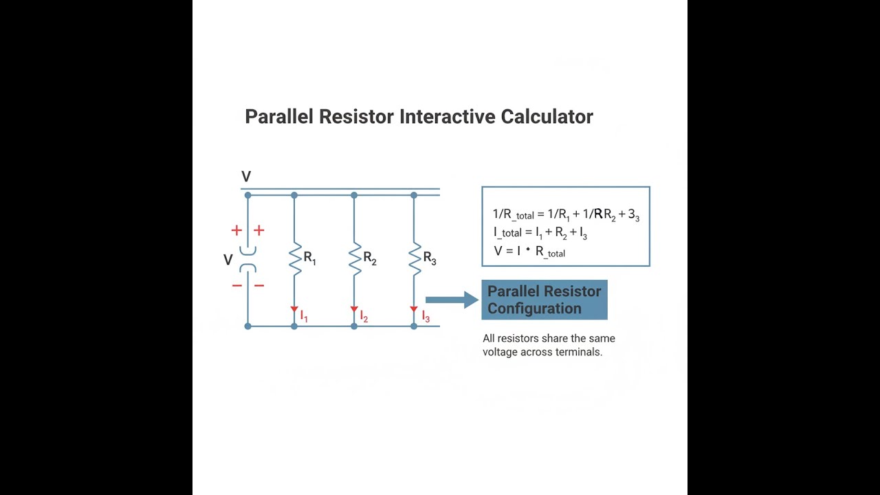
Parallel resistance means you connect two or more resistors between the same two points—they all share the same voltage, and the current divides between them. The total resistance is always less than any one of the resistors you used.
Simple Explanation
If you've got multiple resistors in parallel, think of it like adding lanes to a road: more lanes mean traffic moves easier, so resistance drops as you add rows. Each resistor is its own current path. All the paths see exactly the same voltage—what changes is how much current flows in each, depending on their value.
📐 Browse all 1000+ Interactive Calculators
Parallel Resistor Circuit Diagram

Parallel Resistor Interactive Calculator
How to Use This Calculator
This calculator is intended for education, concept evaluation, and preliminary design. Results are based on the equations and assumptions described on this page, but cannot account for every real-world load case, tolerance, material property, environmental condition, installation detail, safety factor, code, or regulatory requirement. Verify all inputs, assumptions, units, and results independently before selecting components or using the result in a real application. Safety-critical, structural, medical, lifting, transportation, or regulated applications must be reviewed by a qualified engineer.
- Pick your calculation type—equivalent resistance, currents, power, conductance etc—from the dropdown.
- Type in resistor values in ohms. R1 and R2 are required, the rest are optional.
- Put in supply voltage if your mode needs it.
- Hit Calculate for the answer.
Parallel Resistor Interactive Visualizer
The animation below demonstrates in real time how adding more resistors in parallel reduces the overall resistance and allows more current through, while showing what happens to current and power across each resistor.
EQUIVALENT
54.5Ω
TOTAL CURRENT
220mA
TOTAL POWER
2.64W
CONDUCTANCE
18.3mS
FIRGELLI Automations — Interactive Engineering Calculators
Parallel Resistor Equations & Formulas
The formulas below get you your equivalent resistance, current, or power when running parallel resistors.
Equivalent Resistance (General Form):
1/Req = 1/R1 + 1/R2 + 1/R3 + ... + 1/Rn
Two Resistors (Product-over-Sum):
Req = (R1 × R2) / (R1 + R2)
Voltage Relationship:
VR1 = VR2 = VR3 = Vsource
Current Division (Ohm's Law):
In = V / Rn
Total Current:
Itotal = I1 + I2 + I3 + ... + In
Power Dissipation in Each Resistor:
Pn = V2 / Rn = In2 × Rn = V × In
Total Conductance:
Gtotal = G1 + G2 + G3 + ... + Gn
where Gn = 1/Rn
Where:
- Req = Equivalent resistance (Ω)
- R1, R2, Rn = Individual resistances (Ω)
- V = Voltage across parallel resistors (V)
- In = Current through resistor n (A)
- Itotal = Total current from source (A)
- Pn = Power dissipated in resistor n (W)
- Gn = Conductance of resistor n (S, siemens)
Simple Example
Say you have three parallel resistors: 100Ω, 200Ω, 300Ω, on 12V:
- Req = 1 / (1/100 + 1/200 + 1/300) ≈ 54.55Ω
- I₁ = 12V / 100Ω = 120mA, I₂ = 60mA, I₃ = 40mA
- Total current = 220mA
- Total power = 12V × 220mA = 2.64W
Theory & Practical Applications of Parallel Resistor Networks
You'll see parallel resistor setups anywhere current has to split up, loads need balancing, or impedance matching matters. Not like series where current stays the same and voltage changes; with parallel, voltage across every branch stays fixed and it's the current that splits, depending on the resistance of each branch. This is a key idea in splitting up a power supply bus, making current sources, or adding some tolerance to a circuit so a single fault doesn't knock the whole thing out.
Fundamental Physics of Parallel Resistance
The math for parallel resistance comes right out of Kirchhoff's Current Law: the sum of currents into a node equals zero. At your junction, the supply current is split into the branch currents. Each branch gets the same voltage, and Ohm's Law then gives you the current in each. If you add up the reciprocals of each resistance (conductance), then flip the sum, you get total resistance for the network. More parallel paths means more overall conductance—so resistance can only go down as you add resistors. For two equal-value resistors, your total resistance is half of one; for three it's a third, and so on—the more you add, the lower the resistance drops, proportional to how many branches you've got (if they're the same value).
Current Division and Load Sharing
For parallel setups, the lower the resistance in a branch, the more current it takes. Take two branches: the current in one winds up proportional to the other resistor’s value, not its own. If you’re distributing serious current, such as in battery systems or heavy duty controls, you’ll often rely on parallel resistors to keep the load within component ratings. But when tolerances differ, current doesn’t split equally. For example, if you use four “identical” resistors but one measures 10% lower, that branch will get more current, heat up faster, and can start a thermal imbalance. You’ll have to keep this risk in mind.
Power Dissipation and Thermal Management
When you look at heat in parallel resistors, use P = V²/R for each resistor—so the lower the resistance, the more heat it makes (when voltage is constant). That's the opposite of what you get in series assemblies, so don’t overlook it. With 12V across 100Ω and 200Ω in parallel, the 100Ω gets twice the heating, despite being the “easier” path. That’s sometimes intentional, like in shunt resistors for current sensing (where you want very little loss), or when you need to spread the heat—multiple high-value resistors in parallel share the dissipation, making sure you don't burn out individual parts.
Worked Engineering Example: LED Driver Current Distribution
A 24V LED system splits 360mA between three branches, each branch with a resistor to set current. LED string drops 18.5V at the working point. This is the sort of problem you’d get trying to make all three branches share current evenly and working out the resistor values and their power:
Step 1: Target current per branch
Each gets 120mA if split equally: 360mA / 3
Step 2: Voltage across current-limiting resistors
Subtract LED forward voltage: 24V - 18.5V = 5.5V across each resistor
Step 3: Required resistance per branch
R = 5.5V / 0.120A = 45.83Ω
You'll typically pick the next E24 value, 47Ω, which is close enough for LEDs.
Step 4: Actual current with standard resistor
I = 5.5V / 47Ω = 117.0mA per branch, so total about 351mA
Step 5: Power dissipation per resistor
P = (5.5V)² / 47Ω ≈ 0.644W
A 1W resistor is recommended for some overhead.
Step 6: Total system power loss
Power loss in resistors: 3 × 0.644W = 1.93W
LED power: 3 × (18.5V × 0.117A) = 6.50W
Total consumed power: 8.43W; of that, nearly a quarter is wasted as heat in the resistors.
Step 7: Tolerance analysis
If your resistors are 5% tolerance (44.65Ω to 49.35Ω):
High side current: 5.5V / 44.65Ω = 123.2mA
Low side current: 5.5V / 49.35Ω = 111.5mA
Branches might end up with more than 10% difference in current, just due to resistor variation.
That’s why if you want very equal currents—like for matched LED brightness in higher-end jobs—you’re better off with active drivers, not just passive resistor current sharing.
Industrial Applications Across Sectors
Power Distribution: In high-voltage substations, parallel resistor banks limit how much current a ground fault sees—multiple units share both the heat and the risk, so if one burns out, the rest keep things safe (resistance barely changes if a few drop out).
Test and Measurement: If you want a low-value, stable current shunt, you can parallel matched resistors; that improves stability and allows for more current without overheating, and you can use a 4-wire Kelvin setup to knock out the error from PCB traces or solder joints.
EV Battery Management: Car battery packs use lots of cells in parallel, so if one cell gets weak, the load is picked up by its neighbors. Parallel resistors can also help balance charge between cells by bleeding off small differences—just watch the power rating and leakage loss over time.
RF/Microwave Engineering: In radio work, you can parallel resistors to hit nonstandard values for impedance matching. At high frequencies, resistor layout and parasitics start to matter, so surface-mount thin film types are common to keep inductance and capacitance low.
Test/Burn-in: High-volume device test systems use big resistor boards to simulate loads in parallel, so failures can be spotted by measuring current through each resistor. This setup also makes it easy to isolate which device has failed without bringing down the entire test rack.
Non-Ideal Behaviors and Practical Limitations
Real resistors aren’t perfect. At high frequencies, their inductance and parasitic capacitances start to matter. For through-hole resistors, you’ll see 10–20nH stray inductance—harmless in audio but a problem in the MHz to GHz range where impedance gets unpredictable. Paralleling lots of resistors tames inductance but adds up any parasitic capacitance, potentially creating resonant dips or peaks.
When things heat up, resistor values can drift—if one runs hotter, its value might rise, which shifts current to the others, or vice versa, depending on your coefficient. This can start a cycle where current and resistance chase each other in small thermal oscillations, which is an issue in ultra-stable circuits.
Don’t forget voltage coefficient, especially if you’re working with thick-film resistors. Resistance can change with applied voltage—a modest effect at low voltage but a real headache for divider chains above a few hundred volts. Metal film and wirewound types are better behaved here.
Optimization Strategies for Robust Design
If you’re chasing precision, don’t just look at worst-case tolerances. If you parallel n resistors, and they come from different production lots, the statistical tolerance is smaller than for any one resistor alone. But if they’re all from the same reel and run high or low together, this benefit goes away, so be deliberate about sourcing.
In power applications, don’t average the power between branches and call it good. With tolerances, one resistor might take more than its share and overheat. If you want to play it safe, derate each to half their nominal rating in a parallel bank whenever you have more than tiny variation between them.
If you want more practical circuit tools—including series-parallel routines, more divider calculators, and design helpers—check the engineering calculator library.
Frequently Asked Questions
Free Engineering Calculators
Explore our complete library of free engineering and physics calculators.
Browse All Calculators →🔗 Explore More Free Engineering Calculators
- Wheatstone Bridge Calculator
- Resistor Color Code Calculator
- Low-Pass RC Filter Calculator — Cutoff Frequency
- Capacitor Charge Discharge Calculator — RC Circuit
- Bridge Rectifier Calculator
- Eirp Calculator
- Resistor Noise Calculator
- Voltage Divider Calculator
- Voltage Divider & ADC Resolution Calculator
- Transformer Turns Ratio Calculator
About the Author
Robbie Dickson — Chief Engineer & Founder, FIRGELLI Automations
Robbie Dickson brings over two decades of engineering expertise to FIRGELLI Automations. With a distinguished career at Rolls-Royce, BMW, and Ford, he has deep expertise in mechanical systems, actuator technology, and precision engineering.
Need to implement these calculations?
Explore the precision-engineered motion control solutions used by top engineers.


