Connecting inductors in parallel is a core technique when you need to reduce equivalent inductance, share current across components, or hit a value not available off the shelf. Use this Parallel Inductors Calculator to calculate equivalent inductance using individual inductor values, find a missing inductor value from a known equivalent, or analyze quality factor using inductance, ESR, and frequency inputs. It's essential in power electronics, RF circuit design, and multiphase converter development. This page includes the governing formulas, a worked multiphase buck converter example, full theory on coupling and high-frequency parasitics, and an FAQ.
What is parallel inductance?
Parallel inductance is the combined inductance you get when two or more inductors share the same two nodes in a circuit. The result is always lower than the smallest individual inductor — more inductive paths means less total opposition to changing current.
Simple Explanation
Think of inductors like narrow pipes resisting water flow. Put two pipes side by side and water flows more easily — the combined resistance drops. Parallel inductors work the same way: each added inductor gives current another path, so the total inductance falls. The more inductors you add in parallel, the lower the combined value.
📐 Browse all 1000+ Interactive Calculators
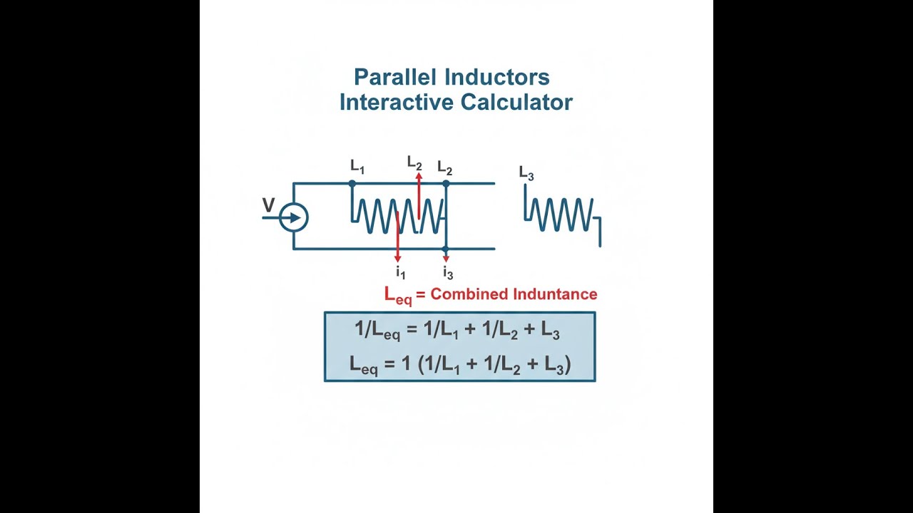
Circuit Diagram: Parallel Inductors

Parallel Inductors Calculator
How to Use This Calculator
- Select your calculation mode from the dropdown — two inductors, three inductors, N identical inductors, reverse-solve for a missing value, or quality factor analysis.
- Enter your inductor values in mH. For quality factor mode, also enter ESR in ohms and frequency in kHz.
- If you want to try a pre-loaded example first, click Try Example to populate the fields automatically.
- Click Calculate to see your result.
Parallel Inductors Interactive Visualizer
Watch how parallel inductors reduce total inductance as current finds multiple paths. Adjust individual inductor values to see real-time equivalent inductance calculations and current distribution across branches.
EQUIVALENT L
18.8 mH
I₁ CURRENT
7.5 A
I₂ CURRENT
12.5 A
FIRGELLI Automations — Interactive Engineering Calculators
Governing Equations
Use the formula below to calculate equivalent inductance for two parallel inductors.
Two Inductors in Parallel
1/Leq = 1/L1 + 1/L2
Leq = (L1 × L2) / (L1 + L2)
Where:
- Leq = Equivalent inductance (H, mH, μH)
- L1, L2 = Individual inductances (same units)
N Inductors in Parallel (General Form)
Use the formula below to calculate equivalent inductance for any number of parallel inductors.
1/Leq = 1/L1 + 1/L2 + 1/L3 + ... + 1/Ln
For N identical inductors: Leq = L / N
Quality Factor and Reactance
Use the formula below to calculate inductive reactance and quality factor.
XL = 2πfL = ωL
Q = XL / RESR = ωL / RESR
Where:
- XL = Inductive reactance (Ω)
- f = Frequency (Hz)
- ω = Angular frequency = 2πf (rad/s)
- L = Inductance (H)
- Q = Quality factor (dimensionless)
- RESR = Equivalent series resistance (Ω)
Simple Example
Two inductors in parallel: L₁ = 10 mH, L₂ = 15 mH.
Leq = (10 × 15) / (10 + 15) = 150 / 25 = 6 mH
The result is smaller than both L₁ and L₂ — as expected for any parallel inductor combination.
Theory & Practical Applications
Fundamental Physics of Parallel Inductance
When inductors are connected in parallel, they share the same voltage but carry independent currents. The total magnetic flux linkage in the circuit is determined by the sum of individual inductor contributions, leading to the reciprocal addition law. This differs fundamentally from series inductors, where flux linkages add directly. The physical origin lies in Faraday's law: each inductor generates a back-EMF proportional to its current rate of change, and in parallel, these back-EMFs must be equal (same voltage across branches). The current division among parallel inductors follows from Kirchhoff's current law and the inductive voltage-current relationship v = L(di/dt).
A critical but often overlooked aspect: parallel inductors only combine according to the reciprocal formula when their magnetic fields are uncoupled. If two inductors are physically close enough to experience mutual inductance (coefficient M), the effective parallel inductance becomes Leq = (L₁L₂ - M²)/(L₁ + L₂ - 2M). In power electronics layouts, designers must maintain adequate spacing or use orthogonal winding orientations to minimize mutual coupling, which can increase effective inductance by 15-30% and introduce unpredictable resonances.
High-Frequency Behavior and Parasitic Effects
Real inductors deviate from ideal behavior due to parasitic capacitance, skin effect, and proximity effect. The self-resonant frequency (SRF) occurs when the inductor's parasitic capacitance resonates with its inductance, beyond which the component behaves capacitively. For parallel configurations, the combined SRF is generally higher than individual SRFs if parasitic capacitances don't add—this is advantageous in RF applications. However, at frequencies approaching SRF, the effective inductance deviates significantly from low-frequency values, and phase response becomes complex.
Skin effect causes AC current to concentrate near conductor surfaces, increasing effective resistance with frequency. In parallel configurations with identical inductors, skin effect reduces each branch's Q-factor equally, but current division remains balanced. Asymmetric parallel combinations (different wire gauges or core materials) can experience unequal current sharing at high frequencies, with lower-ESR branches carrying disproportionate current. Power electronics designers use this deliberately: paralleling a ferrite-core inductor (high L, high ESR) with an air-core inductor (low L, low ESR) provides high DC inductance with improved high-frequency ripple rejection.
Practical Applications in Power Electronics
Parallel inductors are ubiquitous in multiphase DC-DC converters, where N phases operate out-of-phase with identical inductors. The effective ripple inductance seen by the output capacitor is L/N, enabling faster transient response and smaller output capacitors. For example, a six-phase converter with 1 μH per phase presents 167 nH effective ripple inductance—a 6× improvement in di/dt capability. The trade-off is increased component count and PCB area, justified in high-performance computing applications where load steps exceed 100 A/μs.
In filter design, parallel inductors create notch filters when combined with capacitors. A practical example: switching power supplies often use a differential-mode choke (two coupled inductors) in parallel with a common-mode choke. The differential-mode path sees reduced inductance for fast transient response, while the common-mode path maintains high impedance for EMI suppression. This topology is standard in automotive buck converters operating in noisy electrical environments.
Magnetic Core Considerations
When using ferrite or powder-core inductors in parallel, core saturation must be analyzed per-branch. If one inductor saturates (permeability collapse), its inductance drops dramatically, forcing the remaining branches to carry higher current—potentially causing cascade saturation. Designers address this with current-sharing techniques: using inductors with matched saturation characteristics, or deliberately choosing cores with gradual saturation curves (e.g., iron powder vs. ferrite) to prevent abrupt transitions.
Temperature effects also impact parallel current sharing. Inductors with positive temperature coefficient of inductance (most ferrites) increase inductance when hot, reducing their current share—creating negative feedback that balances temperatures. Conversely, air-core or ceramic-core inductors have minimal temperature dependence, requiring external current balancing in high-power parallel arrays.
Worked Example: Multiphase Buck Converter Design
Scenario: Design the output filter for a four-phase synchronous buck converter supplying 12V output at 50A continuous, 80A peak. Input voltage is 48V, switching frequency 300 kHz. Specify per-phase inductance to achieve 20% ripple current per phase, then calculate equivalent output inductance.
Step 1: Calculate per-phase current
Each phase carries Iphase = Iout/N = 50A / 4 = 12.5A average
Ripple current specification: ΔIphase = 0.20 × 12.5A = 2.5A
Step 2: Determine duty cycle
For buck converter: D = Vout/Vin = 12V / 48V = 0.25
Step 3: Calculate required per-phase inductance
Buck inductor ripple equation: L = Vout(1-D) / (fsw × ΔI)
L = 12V × (1-0.25) / (300,000 Hz × 2.5A)
L = 12V × 0.75 / 750,000 A/s
L = 9V / 750,000 A/s = 12 μH per phase
Step 4: Calculate equivalent output inductance
For N identical parallel inductors: Leq = L / N = 12 μH / 4 = 3 μH
Step 5: Verify output ripple current
The phases operate 90° out-of-phase. Instantaneous output ripple is significantly less than algebraic sum due to phase cancellation. For four phases with equal inductance, ripple reduction factor is approximately 4×. Effective output ripple: ΔIout ≈ ΔIphase/4 = 2.5A / 4 = 0.625A, or 1.25% of 50A output—well below typical 5% specifications.
Step 6: Core selection and saturation check
Choose iron-powder toroid cores rated for 15A peak (20% margin). At 12.5A + 1.25A ripple = 13.75A peak, cores operate at 92% of rating. Saturation flux density Bsat for iron powder is typically 1.2-1.5T. Calculate required core area-turns product: AL × N² = 12 μH. Select T106-26 core (AL ≈ 100 nH/turn²), requiring N = √(12,000nH / 100nH) ≈ 11 turns.
Step 7: ESR and quality factor analysis
At 300 kHz, iron-powder core ESR ≈ 0.040Ω (datasheet). Inductive reactance: XL = 2π × 300,000 Hz × 12×10⁻⁶ H = 22.6Ω
Quality factor: Q = 22.6Ω / 0.040Ω = 565—excellent for power inductors.
Practical outcome: Four 12 μH inductors in parallel provide 3 μH effective output inductance with inherent phase cancellation, enabling a small 47 μF ceramic output capacitor (instead of 220 μF required for single-phase at same ripple). This demonstrates why multiphase parallel-inductor architectures dominate high-current, fast-transient applications like CPU VRMs and GPU power supplies.
Design Trade-offs and Limitations
While parallel inductors reduce equivalent inductance and improve current handling, they introduce practical challenges. PCB routing complexity increases with branch count—each phase requires low-resistance traces to prevent current imbalance. Thermal management becomes critical: hot spots in one branch cause inductance mismatch and current redistribution. In automotive applications operating over -40°C to +125°C, temperature-induced inductance variation of ±15% is common, requiring robust control algorithms.
Cost analysis often favors fewer larger inductors over many small ones. A single 10A inductor typically costs less than two 5A inductors, and occupies less board area when accounting for spacing requirements. Parallel configurations are economically justified when: (1) standard values don't meet requirements, (2) multiphase switching provides inherent ripple cancellation, or (3) thermal distribution across multiple components improves reliability. Visit the engineering calculator hub for related inductor design tools including series inductance, LC resonance, and inductor energy storage calculators.
Frequently Asked Questions
Free Engineering Calculators
Explore our complete library of free engineering and physics calculators.
Browse All Calculators →🔗 Explore More Free Engineering Calculators
- Resistor Color Code Calculator
- I2C Pull-Up Resistor Calculator
- I2C/SPI Bus Speed & Pull-up Resistor Sizing
- Capacitor Charge Discharge Calculator — RC Circuit
- Eirp Calculator
- Internal Resistance Calculator
- Noise Figure Calculator
- Voltage Divider Calculator — Output Voltage from Two Resistors
- Ohm's Law Calculator — V I R P
- Transformer Turns Ratio Calculator
About the Author
Robbie Dickson — Chief Engineer & Founder, FIRGELLI Automations
Robbie Dickson brings over two decades of engineering expertise to FIRGELLI Automations. With a distinguished career at Rolls-Royce, BMW, and Ford, he has deep expertise in mechanical systems, actuator technology, and precision engineering.
Need to implement these calculations?
Explore the precision-engineered motion control solutions used by top engineers.


