When building anything from a basic lens to a complex fiber optic run, you’ll hit a point where you can’t just guess how light moves through the interface. The refractive index of every layer is what decides how much a beam bends, where back-reflections go, and how good your focus or transmission will actually be. This calculator lets you quickly find refractive index values, refraction angles, critical angles, and light speed in your materials. In real work, bad index estimates mean you can end up with chromatic blur, fail to achieve total internal reflection, or even send a dangerous laser back-reflection straight into expensive optics. Below you’ll find equations, a step-by-step multi-interface example, practical discussion on dispersion and total internal reflection, and a FAQ for edge cases you’re likely to actually encounter.
What is the Index of Refraction?
The index of refraction (refractive index) tells you how much slower light moves through a material compared to a vacuum. If the index is larger, the light slows down more and bends more at that boundary.
Simple Explanation
Picture light like a car going from a dry road onto thick mud—it slows down and shifts direction. For light, the refractive index is just a way of showing how much slower and how much its path bends in a given material. Air is almost 1 (nearly no change), typical glass is about 1.5 (much slower), and diamond is 2.4 (very slow, which accounts for its sparkle).
📐 Browse all 1000+ Interactive Calculators
Optical Refraction Diagram

Index of Refraction Calculator
How to Use This Calculator
This calculator is intended for education, concept evaluation, and preliminary design. Results are based on the equations and assumptions described on this page, but cannot account for every real-world load case, tolerance, material property, environmental condition, installation detail, safety factor, code, or regulatory requirement. Verify all inputs, assumptions, units, and results independently before selecting components or using the result in a real application. Safety-critical, structural, medical, lifting, transportation, or regulated applications must be reviewed by a qualified engineer.
- Select your Calculation Mode from the dropdown — choose what you want to solve for (index from speed, Snell's law angles, critical angle, etc.).
- Enter the relevant input values that appear — these change depending on your selected mode (e.g., speed of light in medium, refractive indices, or angles).
- Check that all values are physically valid — speeds must be below 299,792,458 m/s, indices must be ≥ 1, and angles must be between 0° and 90°.
- Click Calculate to see your result.
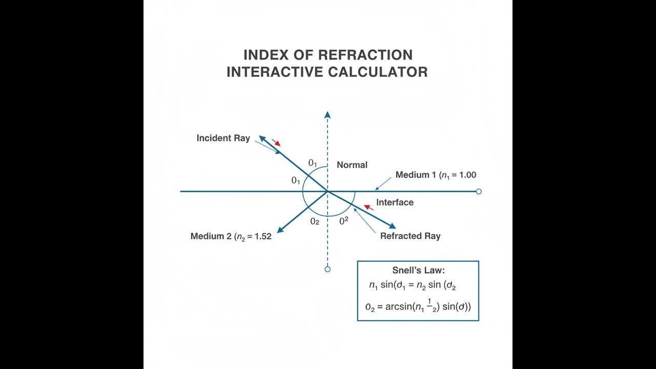
Index of Refraction Interactive Visualizer
This lets you see in real time how refraction depends on the angle of incidence and the indices. Adjust them and you’ll see how the path changes, when the critical angle kicks in, and how material choice sets the limits for what the light will do.
REFRACTION ANGLE
19.5°
CRITICAL ANGLE
41.8°
LIGHT SPEED (M2)
2.0×10⁸
FIRGELLI Automations — Interactive Engineering Calculators
Governing Equations
If you know the speed of light in the material, this gives you refractive index directly.
Refractive Index Definition
n = c / v
Where:
- n = refractive index (dimensionless)
- c = speed of light in vacuum = 299,792,458 m/s
- v = speed of light in the medium (m/s)
Snell’s Law is the one you use every time a beam hits a new material: it tells you the new angle of the transmitted ray.
Snell's Law of Refraction
n₁ sin(θ₁) = n₂ sin(θ₂)
Where:
- n₁ = refractive index of first medium (dimensionless)
- θ₁ = angle of incidence measured from normal (degrees or radians)
- n₂ = refractive index of second medium (dimensionless)
- θ₂ = angle of refraction measured from normal (degrees or radians)
If you want to know at what angle light stops transmitting and is completely reflected (common for fiber and waveguide work), you’ll need the critical angle formula.
Critical Angle for Total Internal Reflection
θc = arcsin(n₂ / n₁)
Where:
- θc = critical angle (degrees or radians)
- n₁ = refractive index of denser medium (dimensionless)
- n₂ = refractive index of less dense medium (dimensionless)
- Condition: n₁ must be greater than n₂ for total internal reflection to occur
Light always shifts wavelength when it enters a new medium, because frequency stays the same but speed goes down. Here’s the relationship.
Wavelength Relationship
λmedium = λvacuum / n
Where:
- λmedium = wavelength in the medium (m)
- λvacuum = wavelength in vacuum (m)
- n = refractive index of the medium (dimensionless)
- Note: Frequency remains constant across boundaries
Simple Example
Light coming from air (n₁ = 1.0) into glass (n₂ = 1.5) at 30° relative to the normal:
Snell’s Law: 1.0 × sin(30°) = 1.5 × sin(θ₂)
sin(θ₂) = 0.5 / 1.5 = 0.333
θ₂ = arcsin(0.333) = 19.47°
The ray bends toward the normal, from 30° down to 19.47°.
Theory & Practical Applications of Refractive Index
Refractive index is just about how fast light really goes, compared to a vacuum, when it travels through a material. Physically, it’s about how electromagnetic waves interact with electrons bound in atoms. As light crosses into a material, it pushes these electrons, generating tiny oscillating dipoles that scatter the wave and slow its phase velocity. The result is a lower speed, but the frequency stays unchanged. For almost any real material, the index is at least one (the same as vacuum) or higher. There are some engineered metamaterials that break this rule, but that’s not what you run into in practical optics most days.
Physical Origin and Dispersion Effects
Refractive index changes with wavelength—sometimes only a little, sometimes enough that you have to design around it. This is called dispersion. It comes from the fact that every material’s electrons respond differently to different frequencies (colors) of light. If you’re near an absorption band, the index can change very quickly with wavelength. That’s a headache in systems where you want sharp focus at all colors. For practical purposes (visible range, clear optical glass), you’ll lean on the Cauchy or Sellmeier equation to relate index to wavelength; every glass type in the catalog comes with its own coefficients, because there is no one-size-fits-all.
For instance, crown glass (n ≈ 1.52 at 589 nm) gives you less dispersion than flint glass (n ≈ 1.62 at 589 nm). If minimizing chromatic blur is your goal, prefer crown. If you’re building achromatic lenses, you’ll combine types specifically because their dispersions go in different directions—what one glass does to red, another cancels for blue.
Snell's Law and Interface Behavior
Whenever light crosses from one material to another with a different refractive index, Snell’s law tells you the new angle. If light moves into a material with a higher index, the beam bends closer to the normal. That’s the core of lens and fiber geometry calculations. But every transition also causes some reflection, according to the index jump at the interface—this is what Fresnel equations are for. By layering coatings with carefully picked index and thickness, you can intentionally boost or suppress this reflection, which is the whole idea behind anti-reflection and high-reflection coatings. These are rarely 100% perfect, and you’ll always have some real reflection unless the index match and angle are just right.
Quarter-wave coatings use interference to suppress reflection across a limited wavelength range. If your system bounces light through many elements (like a multi-lens objective or high-power laser), accounting for even fractions of a percent in reflection becomes necessary—those losses add up quickly.
Total Internal Reflection and Fiber Optics
If you send light from a higher-index material into a lower one at a steep enough angle, it won’t come out the other side at all—everything reflects back in. This is total internal reflection, and it’s how fiber optics actually trap light. A single-mode fiber typically uses a core (n ≈ 1.4682) and a slightly lower-index cladding (n ≈ 1.4628); their small difference sets the critical angle (about 88.7°). Light that stays within this angle won’t leak out after kilometers of travel, allowing very long transmission lengths in telecom. If you’re specifying fiber, check the numerical aperture: NA = √(n₁² - n₂²). For telecom, single-mode fiber is usually about 9 μm in core diameter for 1550 nm light, balanced to support just one mode and maximize bandwidth—too thick, and modal dispersion limits your data rate.
Applications Across Multiple Industries
Refractive index isn’t just for optics labs. Refractometers, which measure index, are used anywhere you need to measure dissolved solids or solution concentration (quality control in food, pharmaceuticals, chemicals). The method is quick and usually accurate to within a fraction of a thousandth in n. Atmospheric refraction shifts apparent position of celestial objects—surveyors and astronomers must correct for this when tracking or measuring long distances. For example, objects at the horizon appear about half a degree above their true position—that’s significant for precise field work.
In high-power laser optics, index can change slightly with intensity due to nonlinear effects. The so-called n₂ coefficient can shift focus or even damage optics if power is high enough, like in pulsed Nd:YAG systems above 10 mJ. You have to factor this in when selecting or specifying coatings for high-peak-power laser surfaces, or else the beam may self-focus and damage your finals lens.
Microscope resolution is ultimately limited by refractive index. Increasing the index of the medium between lens and specimen (like using oil) increases the numerical aperture and lets you see smaller structures. For visible light, standard immersion oil (n ≈ 1.518) lets you push lateral resolution to about 200-250 nm, compared to air (1.0). Going beyond this is only possible with super-resolution techniques, which are still ultimately bound by what index you can realistically achieve with a stable, clear immersion medium.
Worked Example: Multi-Interface Optical System Design
Problem Statement: Suppose you have a 532 nm laser going through air (n = 1.000293 at sea level), then through a BK7 glass window (n = 1.5195 at 532 nm, 3.2 mm thick, window angled at 37.5° to the beam), then into a glycerin solution (n = 1.4746 at 532 nm). The task: (a) find the refraction angles at each interface, (b) compute the lateral beam shift after going through the glass, (c) find the critical angle at the glycerin-to-air exit, (d) estimate how much power is reflected at each interface for unpolarized light.
Part (a): Refraction Angles
First, air to BK7 glass
θ₁ = 37.5°
n₁ sin(θ₁) = n₂ sin(θ₂)
1.000293 × sin(37.5°) = 1.5195 × sin(θ₂)
sin(θ₂) ≈ (1.000293 × 0.6088) / 1.5195 = 0.4006
θ₂ = arcsin(0.4006) ≈ 23.63°
Second, BK7 glass to glycerin
θ₃ = 23.63° (since surfaces are parallel)
1.5195 × sin(23.63°) = 1.4746 × sin(θ₄)
sin(θ₄) ≈ (1.5195 × 0.4006) / 1.4746 = 0.4127
θ₄ = arcsin(0.4127) ≈ 24.36°
Part (b): Lateral Displacement
Path length through the glass: L = t / cos(θ₂) = 3.2 mm / cos(23.63°) ≈ 3.493 mm
Lateral offset: d = L × sin(θ₂) ≈ 3.493 mm × 0.4006 ≈ 1.399 mm
But to get actual shift versus where the beam would’ve emerged without glass:
Displacement = t × sin(θ₁ - θ₂) / cos(θ₂) = 3.2 mm × sin(37.5° - 23.63°) / 0.9161
= 3.2 mm × 0.2395 / 0.9161 ≈ 0.837 mm
Part (c): Critical Angle
For glycerin-to-air (n_glycerin > n_air):
θ_c = arcsin(n_air / n_glycerin) = arcsin(1.000293 / 1.4746) ≈ arcsin(0.6783) ≈ 42.72°
Any internal ray in glycerin hitting the exit interface steeper than this will totally reflect back in—no transmission possible.
Part (d): Fresnel Reflections
Normal-incidence reflection for unpolarized light is R = [(n₂ - n₁) / (n₂ + n₁)]², but for accurate numbers at larger angles, use s- and p-components. Here, just estimate the main contribution:
Air-to-BK7 (θ₁ = 37.5°, θ₂ = 23.63°):
r_s = [n₁cos(θ₁) - n₂cos(θ₂)] / [n₁cos(θ₁) + n₂cos(θ₂)]
r_s = [1.000293 × 0.7934 - 1.5195 × 0.9161] / [1.000293 × 0.7934 + 1.5195 × 0.9161]
r_s = (0.7936 - 1.3920) / (0.7936 + 1.3920) = -0.5984 / 2.1856 = -0.2738
R_s = r_s² = 0.0750 = 7.50%
BK7-to-glycerin
With a smaller jump in index, reflection is much lower:
R ≈ [(1.5195 - 1.4746) / (1.5195 + 1.4746)]² × adjustment ≈ 0.026%
Main power loss is at the air-glass entrance window. In high-power laser setups, you can’t ignore this: that reflected power (even just a few percent) can trigger feedback or damage your source if it returns the wrong way.
Temperature and Pressure Dependence
Refractive index shifts with temperature and pressure, sometimes enough to matter. For most glasses, dn/dT is about -1×10⁻⁵ K⁻¹, meaning the index usually drops as temperature increases. For water and other liquids, the temperature effect is a bit larger, and often with opposite sign. In precision optics—think interferometers or metrology—you control temperature tightly or you’ll lose repeatability at the nanometer scale. With air, keep in mind: index varies with ambient pressure, on the order of Δn = 2.7×10⁻⁷ per millibar. That’s enough to visibly move fringes in a Michelson interferometer if a storm rolls in.
Frequently Asked Questions
Free Engineering Calculators
Explore our complete library of free engineering and physics calculators.
Browse All Calculators →🔗 Explore More Free Engineering Calculators
About the Author
Robbie Dickson — Chief Engineer & Founder, FIRGELLI Automations
Robbie Dickson brings over two decades of engineering expertise to FIRGELLI Automations. With a distinguished career at Rolls-Royce, BMW, and Ford, he has deep expertise in mechanical systems, actuator technology, and precision engineering.
Need to implement these calculations?
Explore the precision-engineered motion control solutions used by top engineers.


