Deploying an ultrasonic sensor without accounting for temperature or time-of-flight math is a fast way to get bad distance readings — especially in environments where ambient conditions shift. Use this Ultrasonic Sensor Time-of-Flight Distance Calculator to calculate object distance using measured echo time and air temperature (or a manually entered speed of sound). It's critical for robotics navigation, industrial automation, and proximity sensing systems where accuracy directly affects mechanical response. This page covers the distance formula, a worked example, temperature compensation theory, and a full FAQ.
What is Ultrasonic Time-of-Flight Distance Measurement?
Ultrasonic time-of-flight distance measurement works by firing a sound pulse and timing how long it takes to bounce back from an object. That round-trip time, combined with the speed of sound, gives you the distance to the target.
Simple Explanation
Think of it like shouting into a canyon and counting the seconds until you hear the echo. The longer it takes, the farther away the wall is. An ultrasonic sensor does the same thing — it sends out a high-pitched sound burst you can't hear, waits for the echo, and uses the travel time to figure out how far away something is. Temperature matters because sound moves faster in warm air than cold air.
📐 Browse all 384 free engineering calculators
Ultrasonic Distance Measurement System
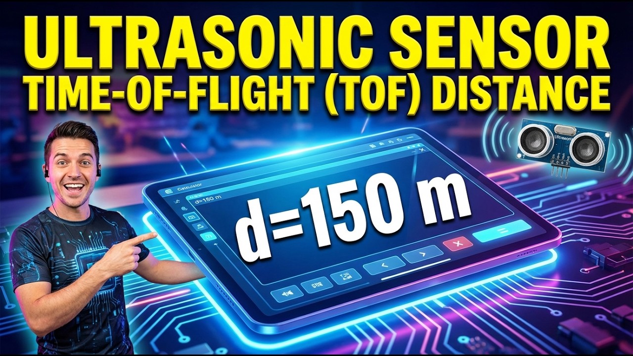
 Distance Calculator | FIRGELLI Engineering Calculator")
Ultrasonic Distance Calculator
📹 Video Walkthrough — How to Use This Calculator
Ultrasonic Time-of-Flight Distance Calculator
See how sound pulses travel and reflect to measure distance. Adjust temperature to watch how air conditions affect sound speed and distance accuracy in real-time.
DISTANCE
34.3 cm
SOUND SPEED
343.4 m/s
ONE-WAY TIME
1.0 ms
FIRGELLI Automations — Interactive Engineering Calculators
How to Use This Calculator
- Enter the time-of-flight value from your ultrasonic sensor in microseconds (μs) in the Time of Flight field.
- Enter the ambient air temperature in degrees Celsius in the Temperature field — the calculator uses this to determine the speed of sound.
- Optionally, enter a known speed of sound value in m/s in the Speed of Sound field if you want to override the temperature-based calculation.
- Click Calculate to see your result.
Mathematical Equations
Primary Distance Calculation:
Use the formula below to calculate distance from time-of-flight and sound velocity.
d = (v × t) ÷ 2
Where:
- d = distance to object (m)
- v = speed of sound (m/s)
- t = time of flight (s)
Speed of Sound in Air:
Use the formula below to calculate the speed of sound from air temperature.
v = 331.3 + 0.606 × T
Where:
- T = temperature (°C)
- 331.3 = speed of sound at 0°C (m/s)
- 0.606 = temperature coefficient (m/s/°C)
Enhanced Speed Formula (with humidity correction):
Use the formula below to calculate speed of sound with humidity correction applied.
v = 331.3√(1 + T/273.15) × (1 + 0.00166 × RH)
Where RH = relative humidity (%)
Simple Example
Sensor detects an object at 20°C. Time of flight = 1,000 μs.
Speed of sound: v = 331.3 + 0.606 × 20 = 343.42 m/s
Time in seconds: 1,000 μs = 0.001 s
Distance: d = (343.42 × 0.001) ÷ 2 = 0.172 m (17.2 cm)
Technical Guide to Ultrasonic Distance Measurement
How Ultrasonic Distance Measurement Works
Ultrasonic distance measurement relies on the principle of acoustic time-of-flight. An ultrasonic transducer emits a high-frequency sound pulse (typically 40 kHz) that travels through air until it encounters an object. The sound wave reflects back to the sensor, which measures the total travel time. Since sound travels at a known velocity through air, we can calculate the distance using this ultrasonic distance calculator.
The fundamental physics involves acoustic wave propagation through a medium. Sound waves are pressure variations that propagate through air at a velocity dependent on the medium's properties—primarily temperature, but also humidity and atmospheric pressure. The round-trip nature of the measurement means we must divide the total time by two to obtain the actual distance to the target.
Factors Affecting Sound Velocity
Temperature: The most significant factor affecting sound speed in air. For every degree Celsius increase in temperature, sound velocity increases by approximately 0.606 m/s. This relationship is nearly linear within normal operating temperatures (-20°C to +60°C).
Humidity: Increased water vapor content reduces air density, slightly increasing sound velocity. The effect is typically 1-2% variation across humidity ranges from 10% to 90% RH.
Atmospheric Pressure: Has minimal effect at constant temperature, as both air density and bulk modulus change proportionally.
Practical Applications
Ultrasonic distance sensors are widely used in robotics, automation, and industrial applications:
- Robotic Navigation: Mobile robots use ultrasonic sensors for obstacle detection and mapping. When integrated with FIRGELLI linear actuators, these systems can automatically adjust mechanical components based on proximity measurements.
- Level Monitoring: Tank level measurement in industrial processes, where the sensor measures distance to liquid surface.
- Automated Parking Systems: Vehicle proximity detection for automated parking assistance.
- Assembly Line Automation: Part detection and positioning in manufacturing systems.
- Security Systems: Motion detection and perimeter monitoring applications.
Worked Example
Consider an ultrasonic sensor detecting an object at room temperature (22°C). The sensor measures a time-of-flight of 5,800 microseconds.
Step 1: Calculate sound velocity
v = 331.3 + 0.606 × 22 = 331.3 + 13.33 = 344.63 m/s
Step 2: Convert time to seconds
t = 5,800 μs = 5,800 × 10⁻⁶ s = 0.0058 s
Step 3: Calculate distance
d = (344.63 × 0.0058) ÷ 2 = 1.999 ÷ 2 = 1.000 m
Therefore, the object is exactly 1.0 meter away from the sensor.
Design Considerations and Best Practices
Sensor Selection
Choose ultrasonic sensors based on required range, resolution, and beam angle. Narrow beam sensors provide better directional accuracy but may miss small objects. Wide beam sensors detect smaller objects but have reduced range precision.
Environmental Compensation
For high-accuracy applications, implement temperature compensation using the formulas in this ultrasonic distance calculator. Consider adding humidity sensors for environments with significant moisture variation.
Signal Processing
Implement digital filtering to reduce noise and false readings. Multiple measurements with statistical analysis improve reliability. Consider using median filtering to eliminate outliers caused by acoustic interference.
Mechanical Integration
When integrating ultrasonic sensors with motion systems, proper mounting is crucial. Vibration from FIRGELLI linear actuators or other mechanical components can affect sensor accuracy. Use vibration dampening mounts and ensure sensor faces remain perpendicular to target surfaces.
Limitations and Considerations
Minimum Range: Most ultrasonic sensors have a "blind zone" typically 2-50cm where measurements are unreliable due to transducer ringing.
Surface Properties: Sound-absorbing materials (foam, fabric) may not reflect sufficient energy. Angled surfaces may reflect sound away from the sensor.
Multiple Reflections: In enclosed spaces, sound may bounce multiple times before returning, causing erroneous readings.
Interference: Multiple ultrasonic sensors operating simultaneously can cause cross-talk. Use different frequencies or time-division multiplexing.
Advanced Applications
Modern automation systems combine ultrasonic sensors with servo controllers and linear actuators for sophisticated positioning systems. For example, a parts handling system might use ultrasonic feedback to precisely position a linear actuator, ensuring consistent part placement regardless of variations in part dimensions.
In quality control applications, arrays of ultrasonic sensors can create detailed profiles of manufactured parts, detecting dimensional variations that would be missed by single-point measurements. The data from this ultrasonic distance calculator becomes input for automated sorting and rejection systems.
Integration with Control Systems
Most ultrasonic sensors provide analog voltage outputs proportional to distance, digital outputs for threshold detection, or serial communication for advanced features. When interfacing with microcontrollers or PLCs, consider the update rate requirements—typical sensors provide measurements at 10-50 Hz, suitable for most automation applications.
For systems requiring higher accuracy or environmental compensation, many sensors accept temperature input signals, automatically adjusting their internal calculations. This eliminates the need for external compensation using formulas from this calculator.
Frequently Asked Questions
📐 Explore our full library of 384 free engineering calculators →
About the Author
Robbie Dickson
Chief Engineer & Founder, FIRGELLI Automations
Robbie Dickson brings over two decades of engineering expertise to FIRGELLI Automations. With a distinguished career at Rolls-Royce, BMW, and Ford, he has deep expertise in mechanical systems, actuator technology, and precision engineering.
Need to implement these calculations?
Explore the precision-engineered motion control solutions used by top engineers.


