If you move a light, speaker, or any similar source farther away, the drop in intensity can catch people out—it's not a linear decrease. As soon as you double the distance, you only get a quarter of the original intensity. That's the inverse square law. If you forget about this, you run the risk of blown-out photos, misjudged treatment doses, or radio emissions that fail the compliance lab. The calculator below lets you work out intensity at a new distance, solve for unknown distance, estimate source power, or compare intensity ratios, depending on what information you've got on hand. This law comes up all over the place—from setting up lights in a photo studio, to doing field measurements for acoustic or RF systems, to following protocols for safe radiation levels. The rest of the page covers the working equations, a step-by-step numerical example, the theory in detail, and an FAQ covering points like lasers, dB scaling, and real-world measurement pitfalls.
What is the Inverse Square Law?
The inverse square law says that physical intensity (whether it's light, sound, radiation, or gravity) falls off with the square of the distance from the source. If you double the distance, you end up with one fourth of the intensity. It's a basic geometric result, not something that only shows up in textbooks.
Simple Explanation
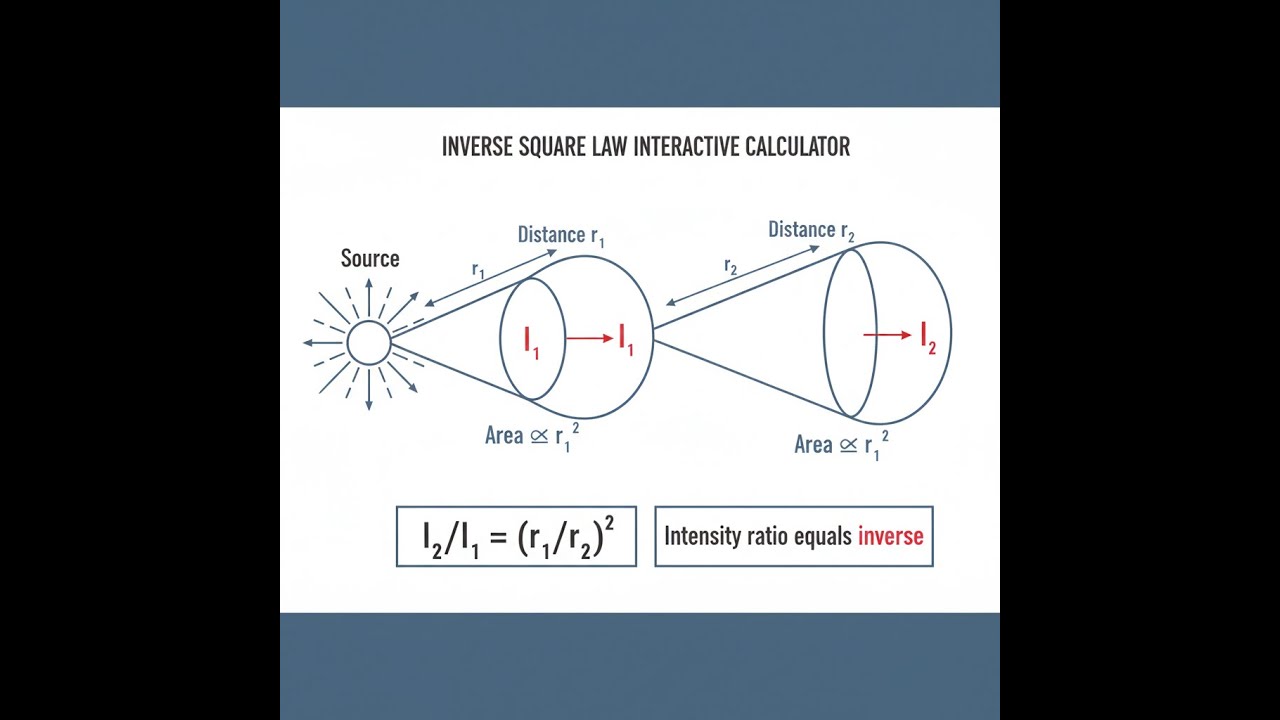
Take a single bulb shining evenly in all directions. As you move farther from the bulb, the same amount of light is spread over a bigger area—the surface of an imaginary sphere centered on the bulb and growing with distance. When you double how far away you are, that invisible sphere is four times bigger in area, so the part of the light hitting a given surface drops to a quarter. That's the core of the inverse square law: the source output doesn't change, just the area you need to spread it over gets a lot bigger.
📐 Browse all 1000+ Interactive Calculators
Table of Contents
How to Use This Calculator
- Pick your Calculation Mode to solve the value you're after (intensity, distance, ratio, or source power).
- Type in the intensity (I₁) at your reference distance using units that fit your job—W/m², lux, dB, etc.
- Enter distance values (r₁ and/or r₂) in the same unit system—meters, feet, whatever, so long as both match.
- Click Calculate and read your result.
Simple Example
Suppose a light source gives you 100 lux at 1 m. What intensity shows up at 2 m?
- I₁ = 100 lux, r₁ = 1 m, r₂ = 2 m
- I₂ = 100 × (1/2)² = 100 × 0.25 = 25 lux
So, doubling the distance dropped you to 25% of the starting intensity—just what the inverse square law calls for.
Inverse Square Law Diagram

Interactive Inverse Square Law Calculator
This calculator is intended for education, concept evaluation, and preliminary design. Results are based on the equations and assumptions described on this page, but cannot account for every real-world load case, tolerance, material property, environmental condition, installation detail, safety factor, code, or regulatory requirement. Verify all inputs, assumptions, units, and results independently before selecting components or using the result in a real application. Safety-critical, structural, medical, lifting, transportation, or regulated applications must be reviewed by a qualified engineer.
Inverse Square Law Interactive Visualizer
You can see with your own eyes how intensity drops off quickly as you move away from a point source. Drag the distance slider to observe how much weaker light, sound, or radiation gets as the area increases.
INTENSITY
7.96 W/m²
SURFACE AREA
50.3 m²
RELATIVE %
25%
FIRGELLI Automations — Interactive Engineering Calculators
Governing Equations
The equations below let you get intensity, distance, or source power using the inverse square law directly.
Inverse Square Law (General Form):
I = P / (4πr²)
Intensity Ratio Form:
I₂/I₁ = (r₁/r₂)²
Distance Calculation:
r₂ = r₁ × √(I₁/I₂)
Variable Definitions:
- I = Intensity at distance r (W/m², lux, dB, or appropriate unit)
- I₁ = Intensity at reference distance r₁
- I₂ = Intensity at comparison distance r₂
- P = Total source power (W or appropriate unit)
- r = Distance from point source (m, ft, or consistent unit)
- r₁ = Reference distance from source
- r₂ = Comparison distance from source
Key Relationships:
Doubling distance: Intensity reduces to 1/4 (25% of original)
Tripling distance: Intensity reduces to 1/9 (11.1% of original)
Halving distance: Intensity increases to 4× original (400%)
Solid angle consideration: For spherical radiation, total power distributed over surface area 4πr²
Theory & Practical Applications
Physical Foundation of the Inverse Square Law
The law comes straight from geometry and conservation of energy or field, not from experiment or hunches. If you have a source that radiates equally in all directions, the same total power fills out a bigger and bigger spherical shell as you move away. The area of a sphere is 4πr², so doubling r makes an area four times as large; the same power spreads thinner. The intensity drops as the square of the distance, plain and simple.
This only works perfectly in open space and only when the source is small enough compared to the distance (the "point source" limit). If your measurement is close to a large source, or if something in the air is blocking or scattering what you're measuring, you start getting errors that aren't captured by the basic law. Errors are bigger the closer you are, or if there's noticeable air absorption or scattering—common in real conditions for both sound and EM fields. That's why professionals correct field measurements using published transmission coefficients, and only take readings in the "far field" (several times source size in distance) when strict inverse square law math applies.
Applications in Photographic and Cinematographic Lighting
Photographers use the law to shape light falloff and contrast. If you put a softbox close to a subject for a portrait, light can drop off across just a small part of the face—say, a nose-to-ear span of 0.15 m, which is 25% farther from a 0.6 m source and gives you a roughly 36% drop in intensity (down to 64%). That falloff makes faces look three-dimensional. With lights placed farther away—like 4 m—moving 0.15 m adds only about 4% to distance, so intensity hardly changes. For product shots, people work out exact light ratios by changing distance instead of fiddling with electrical power, which avoids changes in color. This matters most when you need specific contrast and want to keep everything within your camera's limited dynamic range.
Radiation Safety and Medical Dosimetry
In hospitals and labs, the law limits both patient dose and operator exposure. During long X-ray imaging, stepping back from 0.5 m to 1.0 m cuts your exposure to a quarter—it doesn't take much extra distance to make a difference. Treatment plans for radiation therapy use the law to work out where seeds or sources should go, with very tight tolerances: move an iridium-192 seed by 1 mm at a 5 mm treatment site and you get a ~20% error in distance and a 36% swing in dose. The geometry does most of the work, while material corrections or heterogeneity tweaks add minor adjustments.
Acoustic Engineering and Sound Reinforcement
Sound pressure generally follows inverse square behavior outdoors, at least until room reflections overpower the direct sound (the "reverberant field" takes over indoors). For big outdoor gigs, engineers rely on this law to lay out loudspeaker arrays. Line arrays behave more like "line sources" near the stage (drop-off is less steep: 1/r), but switch to 1/r² (point source) farther out; that's why modern concerts favor line arrays for even coverage over deep crowds. In rooms, there's a "critical distance" where the direct sound and room reflections balance—the law is only reliable closer in than that, and critical when placing microphones or speakers in those borderline regions.
Electromagnetic Compliance Testing and Antenna Analysis
EMI labs rely on the law when reporting radio emissions. If equipment is tested at 3 m and the legal spec is for 10 m, the difference is a clean 20log₁₀(r₂/r₁) dB drop—if you're in the far field, which is only true if you're much farther from the circuit than its largest dimension squared divided by wavelength. Ignore this and your compliance prediction can easily be off by several dB. For antenna measurements, absolute gain and power density calculations are all done by comparing received power at a set distance using a reference gain antenna—again, provided you're genuinely far enough away from the antenna (the standard cutoff is 2D²/λ, with D being antenna diameter). This can mean test distances of hundreds of meters for big antennas at high frequency.
Worked Example: Multi-Stage Lighting Design
Problem: A theater lighting designer must illuminate a 2.4 m wide backdrop to achieve 500 lux at center while maintaining maximum 15% intensity variation across the width. The existing inventory includes 2000 W tungsten-halogen Fresnels with 85% lamp-to-beam efficiency. Determine the required fixture distance, verify uniformity, calculate power density at the fixture position, and assess whether moving the fixture 0.5 m closer would maintain acceptable uniformity while achieving higher center intensity.
Given:
- Target center illuminance: I_center = 500 lux
- Backdrop width: w = 2.4 m
- Maximum intensity variation: ±15% (intensity ratio 0.85 to 1.0 at edges relative to center)
- Fixture power: P_total = 2000 W × 0.85 = 1700 W effective
- Assume isotropic radiation for initial calculation (will verify with cosine falloff)
Solution Part 1: Determine fixture distance for center illuminance
Using I = P/(4πr²), solve for r:
r = √[P/(4π×I_center)] = √[1700 W/(4π × 500 W/m²)]
r = √[1700/(6283.2)] = √0.2706 = 0.520 m
This distance would apply for perpendicular incidence at center. For a flat backdrop, we must account for oblique angles at edges.
Solution Part 2: Verify edge uniformity with geometric correction
At the backdrop edge 1.2 m from center, the distance from fixture to edge point is:
r_edge = √(r² + 1.2²) = √(0.520² + 1.44) = √1.710 = 1.308 m
Intensity at edge (inverse square only): I_edge = I_center × (r/r_edge)² = 500 × (0.520/1.308)² = 500 × 0.158 = 79.0 lux
This represents 15.8% of center intensity—far below the 85% requirement. The issue is that placing the fixture at 0.52 m creates severe geometric non-uniformity. We need to increase fixture distance substantially.
For acceptable edge uniformity, require I_edge/I_center ≥ 0.85. Using combined inverse square and cosine law (intensity ∝ cos θ/r² for Lambertian source):
At edge: cos θ_edge = r/r_edge, so I_edge = I_center × (r/r_edge)³ for perpendicular illumination geometry
Setting I_edge/I_center = 0.85:
0.85 = (r/√(r² + 1.44))³
Let x = r²: 0.85 = (x/(x + 1.44))^1.5
0.85^(2/3) = x/(x + 1.44)
0.8987 = x/(x + 1.44)
0.8987x + 1.294 = x
x = 12.78, therefore r = 3.57 m
Solution Part 3: Calculate actual center intensity at 3.57 m
I_center = 1700/(4π × 3.57²) = 1700/159.9 = 10.6 lux
This is far below the 500 lux target. To achieve 500 lux at 3.57 m requires:
P_required = I_center × 4πr² = 500 × 4π × 12.78 = 80,270 W
This is impractical. The designer must either accept lower illuminance, use multiple fixtures, or employ non-uniform illumination with edge feathering.
Solution Part 4: Assess closer positioning at 0.52 - 0.50 = 0.02 m (moving 0.5 m closer from 0.52 m baseline)
Repositioning to r = 0.02 m is physically impossible (fixture would contact backdrop). The question likely intends moving from a larger starting distance. Assuming instead we evaluate moving from r = 2.0 m to r = 1.5 m:
At r = 2.0 m:
I_center = 1700/(4π × 4.0) = 33.8 lux
r_edge = √(4.0 + 1.44) = 2.33 m
I_edge = 33.8 × (2.0/2.33)³ = 33.8 × 0.628 = 21.2 lux (ratio 0.628, below 0.85 target)
At r = 1.5 m:
I_center = 1700/(4π × 2.25) = 60.1 lux
r_edge = √(2.25 + 1.44) = 1.92 m
I_edge = 60.1 × (1.5/1.92)³ = 60.1 × 0.507 = 30.5 lux (ratio 0.507, worse uniformity)
Conclusion: Achieving both 500 lux and 15% uniformity is impossible with a single 1700 W effective source. Professional solution requires either: (1) array of 4-6 fixtures at ≥2.5 m distance, totaling 8-10 kW; (2) acceptance of reduced illuminance target (~50 lux) with single fixture at 2 m; or (3) asymmetric lighting with graduated intensity accepting non-uniform backdrop appearance.
Non-Ideal Behavior and Correction Factors
Real-world use of the law is messy. Things like air humidity or particulate matter absorb and scatter signal (sound or light), producing an exponential decay on top of geometric spreading. For ultrasound at 40 kHz, air can add more than a dB/m of loss—so, after a few meters, you'll see signal fall off faster than 1/r². In those cases, multiply the ideal result by exp(-αr), with α grabbed from reference data for your frequency and air conditions.
Big sources break the point-source assumption up close. For a 0.5 m LED, anything closer than 5 m isn't really the far field—the calculation's off and you need either correction tables or a proper integration over the source. Tools like DIALux lighting software can adjust for this when it matters, as in automotive headlamp testing, where actual intensity patterns at test distances are legally specified and a simple math shortcut never passes inspection.
Need more calculators? The FIRGELLI Engineering Calculator Library has a full set of field analysis, acoustic, and photometric tools for more involved cases.
Frequently Asked Questions
Free Engineering Calculators
Explore our complete library of free engineering and physics calculators.
Browse All Calculators →🔗 Explore More Free Engineering Calculators
About the Author
Robbie Dickson — Chief Engineer & Founder, FIRGELLI Automations
Robbie Dickson brings over two decades of engineering expertise to FIRGELLI Automations. With a distinguished career at Rolls-Royce, BMW, and Ford, he has deep expertise in mechanical systems, actuator technology, and precision engineering.
Video Walkthrough - How to Use This Calculator
Need to implement these calculations?
Explore the precision-engineered motion control solutions used by top engineers.


