Designing optical systems means predicting exactly how light bends at every material boundary — get that wrong and your lens system, fiber coupling, or underwater imaging geometry fails. Use this Angle of Refraction Interactive Calculator to calculate refraction angles, critical angles, Brewster's angle, and refractive indices using Snell's Law with inputs for incident angle, n₁, and n₂. It matters across lens design, fiber optic telecommunications, and precision refractometry. This page covers the core equations, a worked optical fiber example, theory behind dispersion and total internal reflection, and an FAQ.
What is the Angle of Refraction?
The angle of refraction is the angle at which light travels through a new material after crossing a boundary from another material. It is always measured from the normal — an imaginary line perpendicular to the surface at the point where light hits it.
Simple Explanation
Think of light like a car rolling from smooth asphalt onto gravel at an angle — the wheel that hits the gravel first slows down, causing the car to turn. That turn is refraction. The bigger the difference in materials (smooth vs. rough, air vs. glass), the sharper the turn.
📐 Browse all 1000+ Interactive Calculators
How to Use This Calculator
- Select a calculation mode from the dropdown — choose what you want to solve for (refraction angle, incident angle, refractive index, critical angle, or Brewster's angle).
- Enter the incident angle in degrees and the refractive indices n₁ and n₂ for the relevant input fields that appear.
- If you want to try a pre-loaded example first, click the Try Example button to populate the fields automatically.
- Click Calculate to see your result.
Refraction Diagram

Interactive Refraction Calculator
Angle of Refraction Interactive Visualizer
Watch how light bends when crossing material boundaries using Snell's Law. Adjust incident angle and refractive indices to see real-time refraction, critical angle effects, and total internal reflection.
REFRACTION ANGLE
19.5°
CRITICAL ANGLE
41.8°
BREWSTER ANGLE
56.3°
REFLECTION
Normal
FIRGELLI Automations — Interactive Engineering Calculators
Core Equations
Use the formula below to calculate the angle of refraction.
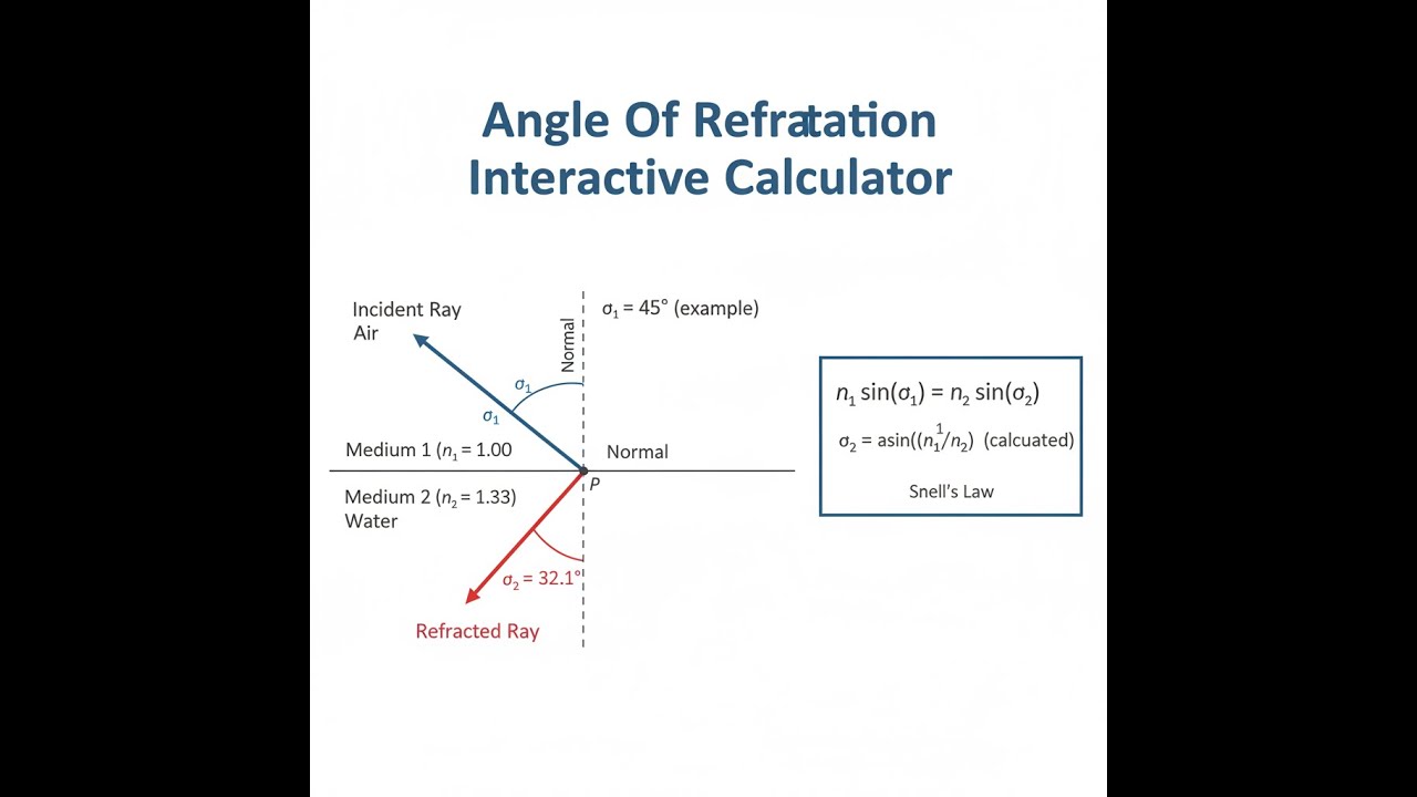
Snell's Law
n₁ sin(θ₁) = n₂ sin(θ₂)
n₁ = refractive index of the first medium (dimensionless)
n₂ = refractive index of the second medium (dimensionless)
θ₁ = angle of incidence measured from the normal (degrees or radians)
θ₂ = angle of refraction measured from the normal (degrees or radians)
Solving for Refraction Angle
θ₂ = arcsin[(n₁/n₂) sin(θ₁)]
Valid only when (n₁/n₂) sin(θ₁) ≤ 1
Critical Angle
θc = arcsin(n₂/n₁)
Exists only when n₁ > n₂ (light traveling from denser to less dense medium)
Beyond this angle, total internal reflection occurs with no refracted ray
Brewster's Angle
θB = arctan(n₂/n₁)
Angle at which reflected light is completely polarized
At this angle, reflected and refracted rays are perpendicular (90° apart)
Simple Example
Light travels from air (n₁ = 1.0) into glass (n₂ = 1.5) at an incident angle of 30°.
sin(θ₂) = (1.0 / 1.5) × sin(30°) = 0.6667 × 0.5 = 0.3333
θ₂ = arcsin(0.3333) = 19.47°
The light bends toward the normal — as expected when entering a denser medium.
Theory & Practical Applications
Fundamental Physics of Refraction
Refraction occurs when electromagnetic waves traverse boundaries between media with different optical densities, causing a change in propagation velocity and consequent directional deviation. The refractive index n quantifies this optical density as the ratio of light speed in vacuum (c) to light speed in the medium (v): n = c/v. Unlike simplified textbook treatments that focus solely on angle calculations, practical optical engineering must account for wavelength dependence (dispersion), polarization effects, and interface quality.
Snell's Law emerges from boundary conditions requiring continuity of the electromagnetic field's tangential components at interfaces. The law maintains the product n sin(θ) constant across boundaries—a direct consequence of phase matching along the interface plane. This constraint means wavefronts arriving at different interface points simultaneously must depart simultaneously, forcing the relationship between angles and refractive indices. For non-normal incidence, the transmitted wave always bends toward the normal when entering a denser medium (higher n) and away from the normal when entering a less dense medium.
Critical Angle and Total Internal Reflection
When light transitions from a higher refractive index medium to a lower one (n₁ > n₂), a critical incident angle θc = arcsin(n₂/n₁) exists beyond which no refracted ray emerges. Instead, all incident energy reflects back into the denser medium—a phenomenon exploited extensively in fiber optic communications and prism-based optical instruments. The fiber optic industry uses silica glass cores (n ≈ 1.458) surrounded by fluorine-doped cladding (n ≈ 1.455) with a critical angle of approximately 83.5°, enabling signals to propagate through kilometers of fiber with minimal loss by maintaining angles beyond this threshold.
Near the critical angle, the refracted ray grazes along the interface (θ₂ → 90°), and the transmitted intensity drops dramatically while reflection coefficient approaches unity. This transition region exhibits strong sensitivity—a mere 0.5° change in incident angle near critical can shift transmission from 15% to total reflection. Precision optical systems must account for this nonlinearity when operating near critical conditions. Evanescent waves exist beyond the interface during total internal reflection, penetrating roughly one wavelength into the less dense medium before decaying—a phenomenon utilized in frustrated total internal reflection sensors and near-field optical microscopy.
Dispersion and Wavelength Dependence
All transparent materials exhibit wavelength-dependent refractive indices due to resonant interactions between electromagnetic fields and bound electrons. Crown glass at 20°C has n = 1.532 at 400 nm (violet) but n = 1.514 at 700 nm (red), causing violet light to refract more strongly than red light—the basis for prism spectroscopy. Optical designers characterize dispersion using the Abbe number Vd = (nd - 1)/(nF - nC), where subscripts reference specific spectral lines. Low Abbe numbers indicate high dispersion, problematic for imaging systems where chromatic aberration degrades resolution by focusing different wavelengths at different positions.
Fiber optic telecommunications must account for chromatic dispersion limiting data rates. The dispersion parameter D (ps/(nm·km)) quantifies pulse broadening per unit wavelength spread per unit length. Standard single-mode fiber has D ≈ 17 ps/(nm·km) at 1550 nm, meaning a 1 nm bandwidth pulse broadens by 17 ps per kilometer. Multi-gigabit systems combat this using dispersion-shifted fibers with D near zero at operating wavelengths, or dispersion compensation modules inserting sections with opposite dispersion sign.
Brewster's Angle and Polarization
At Brewster's angle θB = arctan(n₂/n₁), reflected light becomes completely polarized with electric field perpendicular to the plane of incidence (s-polarized), while transmitted light contains both polarizations but enhanced p-polarized component. This occurs because the reflected and refracted rays become perpendicular—electric dipoles in the material oscillate along the refracted ray direction and cannot radiate back along the reflected ray direction. For an air-glass interface (n₁ = 1.00, n₂ = 1.50), Brewster's angle is 56.3°, explaining why polarizing sunglasses reduce glare from horizontal surfaces like water or roads by blocking s-polarized reflections.
Laser systems employ Brewster windows to minimize reflection losses while selecting polarization. Gas laser tubes terminate with windows cut at Brewster's angle, allowing p-polarized light to pass with near-zero reflection loss (typically 0.01%) while s-polarized light suffers ~15% reflection loss per surface, strongly suppressing this polarization. High-power laser systems cannot tolerate even 4% reflection losses from normal-incidence windows, making Brewster angle geometry essential despite increased complexity.
Industrial Applications
Underwater imaging requires refraction corrections since water-air interfaces create apparent depth distortion. A diver observing a fish at apparent depth dapparent sees it at actual depth dactual = nwater × dapparent ≈ 1.333 × dapparent, causing 33% depth magnification. Submarine periscopes incorporate corrector optics compensating for this effect across the water-air-glass interfaces. Underwater cameras use dome ports rather than flat ports specifically because domes maintain consistent refraction geometry across the field of view, preventing edge distortion that flat ports introduce through angle-dependent refraction.
Precision refractometry measures refractive indices to ±0.00001 for quality control in glass manufacturing, pharmaceutical analysis, and petroleum testing. Modern Abbe refractometers illuminate the sample at the critical angle, measuring the boundary between bright and dark regions to determine n within seconds. The technique exploits the sharp transition at critical angle—small refractive index changes produce easily measured angular shifts. Pharmaceutical companies verify drug purity by measuring solution refractive indices since impurities alter n predictably, enabling detection at parts-per-thousand levels.
Atmospheric refraction affects astronomical observations, surveying, and long-range targeting systems. Earth's atmosphere acts as a gradient-index medium with density decreasing with altitude, causing light rays to follow curved paths. Objects near the horizon appear elevated by approximately 0.5° due to cumulative refraction through atmospheric layers. Surveyors performing geodetic measurements over distances exceeding 1 km must apply refraction corrections to achieve millimeter-level accuracy. Military rangefinders and ballistic computers incorporate atmospheric models predicting refraction based on temperature, pressure, and humidity profiles along the beam path.
Worked Example: Optical Fiber Design
Problem: Design an optical fiber for telecommunications operating at 1550 nm wavelength. The core must support single-mode propagation with total internal reflection ensuring signal confinement. Given: core diameter 9.2 μm, core refractive index ncore = 1.4682, cladding refractive index ncladding = 1.4628. Calculate: (a) critical angle for total internal reflection, (b) numerical aperture determining light-gathering capability, (c) maximum acceptance angle for light entering from air (nair = 1.0003), and (d) verify single-mode operation by calculating the V-number.
Solution:
(a) Critical Angle: Total internal reflection occurs at the core-cladding boundary when incident angles exceed the critical angle.
θc = arcsin(ncladding/ncore) = arcsin(1.4628/1.4682) = arcsin(0.9963) = 85.17°
Light propagating at angles greater than 85.17° from the normal (or within 4.83° of the fiber axis) undergoes total internal reflection, remaining trapped within the core. This extremely shallow guiding angle is characteristic of weakly-guiding fibers optimized for low dispersion.
(b) Numerical Aperture: The numerical aperture (NA) quantifies the light-gathering power, derived from Snell's law at the fiber entrance and critical angle at the core-cladding boundary:
NA = √(n²core - n²cladding) = √(1.4682² - 1.4628²) = √(2.1556 - 2.1398) = √0.0158 = 0.1257
This low numerical aperture (0.13) indicates weak optical confinement but correspondingly low modal dispersion—desirable for long-haul telecommunications. Higher NA fibers (0.3-0.5) used in short-distance multimode applications gather more light but suffer increased modal dispersion limiting bandwidth.
(c) Maximum Acceptance Angle: Light entering from air must satisfy:
nair sin(θmax) = NA
θmax = arcsin(NA/nair) = arcsin(0.1257/1.0003) = arcsin(0.1257) = 7.22°
The acceptance cone half-angle is 7.22°, giving a full cone angle of 14.44°. Laser sources coupling into single-mode fiber must match this acceptance angle through precision optics. Misalignment by even 1° causes coupling efficiency to drop below 50%, explaining why fiber-optic connectors require sub-micron positioning tolerances.
(d) V-Number (Normalized Frequency): Single-mode operation requires V less than 2.405:
V = (2πa/λ) × NA = (2π × 4.6 μm / 1.55 μm) × 0.1257 = 18.66 × 0.1257 = 2.346
where a = 4.6 μm is the core radius. Since V = 2.346 is less than the cutoff value 2.405, this fiber supports only the fundamental LP01 mode at 1550 nm—the definition of single-mode operation. The design operates close to cutoff (V/Vcutoff = 0.976), balancing single-mode operation against reasonable coupling efficiency. Values too far below cutoff (V less than 1.8) make coupling impractically sensitive to alignment, while exceeding 2.405 introduces higher-order modes causing modal dispersion.
This worked example demonstrates how refractive index differences of only 0.37% (54 parts per 10,000) enable global fiber-optic networks carrying terabits per second across oceanic distances. The design balances competing requirements: tight optical confinement requires high index contrast, but single-mode operation demands small core diameter and low index contrast to suppress higher-order modes.
Frequently Asked Questions
▼ Why does light bend when passing between different materials?
▼ What happens when the calculated sine value exceeds 1.0 in Snell's Law?
▼ Does refraction depend on light wavelength or color?
▼ How accurate do refractive index measurements need to be for practical applications?
▼ Why does Brewster's angle matter for laser systems and photography?
▼ How does atmospheric refraction affect precision measurements and astronomy?
Free Engineering Calculators
Explore our complete library of free engineering and physics calculators.
Browse All Calculators →🔗 Explore More Free Engineering Calculators
About the Author
Robbie Dickson — Chief Engineer & Founder, FIRGELLI Automations
Robbie Dickson brings over two decades of engineering expertise to FIRGELLI Automations. With a distinguished career at Rolls-Royce, BMW, and Ford, he has deep expertise in mechanical systems, actuator technology, and precision engineering.
Need to implement these calculations?
Explore the precision-engineered motion control solutions used by top engineers.


