If you’re running a reactor core, you need real numbers for neutron flux—not just rough guesses. This calculator lets you work out neutron flux density, reaction rates, fuel burnup, and power output using practical values like reactor power, core volume, cross section, and atom density. These calculations matter in the day-to-day running of power reactors, research cores, and isotope production units. Below, you’ll find the core equations, an example calculation, details on flux spectra and material effects, and a FAQ grounded in what actually comes up during reactor work.
What is Neutron Flux?
Neutron flux is a measure of how many neutrons are passing through a given area per second inside a reactor. It tells engineers how intensely nuclear reactions are happening in the core — and directly sets the power output, fuel consumption rate, and radiation dose to surrounding materials.
Simple Explanation
Think of neutron flux like water pressure in a pipe — the higher the pressure, the faster things react. In a reactor core, a higher neutron flux means more fissions per second, which means more heat, more power, and faster fuel depletion. Every major reactor decision — how long to run before refueling, how thick to make shielding, how fast materials degrade — comes back to knowing that flux number.
📐 Browse all 1000+ Interactive Calculators
Reactor Flux Diagram

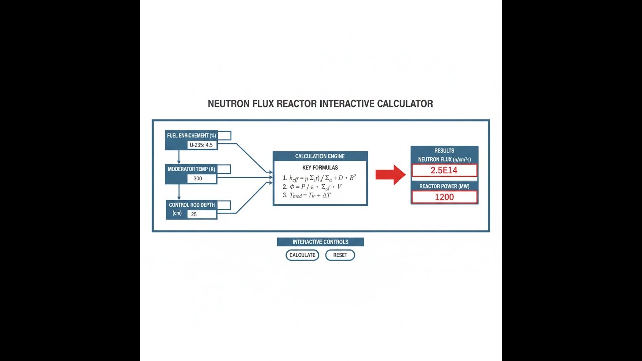
Neutron Flux Reactor Interactive Calculator
How to Use This Calculator
- Select a Calculation Mode from the dropdown — choose from neutron flux, reactor power, reaction rate, fuel burnup, thermal-to-fast flux ratio, or activation rate.
- Enter the required input values for your selected mode — these may include reactor power (MW), core volume (m³), neutron flux (n/cm²·s), cross section (barns), atom density (atoms/cm³), operating time (days), fuel mass (kg), or half-life (days).
- Use the Try Example button to load realistic sample values if you want to see the calculator in action before entering your own data.
- Click Calculate to see your result.
This calculator is intended for education, concept evaluation, and preliminary design. Results are based on the equations and assumptions described on this page, but cannot account for every real-world load case, tolerance, material property, environmental condition, installation detail, safety factor, code, or regulatory requirement. Verify all inputs, assumptions, units, and results independently before selecting components or using the result in a real application. Safety-critical, structural, medical, lifting, transportation, or regulated applications must be reviewed by a qualified engineer.
Neutron Flux Reactor Interactive Visualizer
Watch how neutron flux density drives nuclear reactions in a reactor core, directly controlling power output and fuel burnup rates. Adjust reactor parameters to see real-time calculations of flux distribution, reaction rates, and thermal power generation.
NEUTRON FLUX
5.3×10¹³
POWER DENSITY
10.0 MW/m³
REACTION RATE
3.1×10¹⁹
FIRGELLI Automations — Interactive Engineering Calculators
Fundamental Equations
Use the formula below to calculate neutron flux from reactor power.
Neutron Flux from Reactor Power
Φ = P / (V · Ef · σf)
Where:
- Φ = Average neutron flux (n/cm²·s)
- P = Reactor thermal power (W)
- V = Active core volume (cm³)
- Ef = Energy released per fission (J) ≈ 3.204×10⁻¹¹ J for U-235
- σf = Macroscopic fission cross section (cm-1) ≈ 584.4 barns for thermal U-235
Use the formula below to calculate reaction rate.
Reaction Rate
R = Φ · Σ = Φ · N · σ
Where:
- R = Reaction rate (reactions/cm³·s)
- Φ = Neutron flux (n/cm²·s)
- Σ = Macroscopic cross section (cm-1)
- N = Atomic number density (atoms/cm³)
- σ = Microscopic cross section (cm²) — 1 barn = 10-24 cm²
Use the formula below to calculate fuel burnup.
Fuel Burnup
BU = (P · t) / Mfuel
Where:
- BU = Fuel burnup (MWd/MTU)
- P = Average thermal power (MW)
- t = Operating time (days)
- Mfuel = Initial heavy metal mass (metric tons uranium, MTU)
Use the formula below to calculate neutron activation.
Neutron Activation
A(t) = Φ · σ · N · (1 - e-λt)
Where:
- A(t) = Activity after irradiation time t (Bq/cm³)
- Φ = Neutron flux (n/cm²·s)
- σ = Activation cross section (cm²)
- N = Target atom density (atoms/cm³)
- λ = Decay constant (s-1) = ln(2)/t1/2
- t = Irradiation time (s)
Use the formula below to calculate power density.
Power Density
q''' = P / V
Where:
- q''' = Volumetric power density (MW/m³)
- P = Total reactor thermal power (MW)
- V = Active core volume (m³)
Simple Example
Given: Reactor power = 1000 MW, core volume = 100 m³, energy per fission = 200 MeV.
Power in watts = 1000 × 10⁶ = 1×10⁹ W. Energy per fission in joules = 200 × 1.602×10⁻¹³ = 3.204×10⁻¹¹ J. Fission rate = 1×10⁹ / 3.204×10⁻¹¹ = 3.12×10¹⁹ fissions/s. Core volume in cm³ = 100 × 10⁶ = 1×10⁸ cm³. Average neutron flux ≈ 3.12×10¹⁹ / (1×10⁸ × 584.4×10⁻²⁴) ≈ 5.34×10¹³ n/cm²·s. Power density = 1000 / 100 = 10 MW/m³.
Theory & Engineering Applications
Neutron flux represents the total distance traveled by all neutrons per unit volume per unit time, expressed conventionally as neutrons per square centimeter per second (n/cm²·s). This fundamental quantity directly governs the rate of nuclear reactions within a reactor core and consequently determines power output, fuel consumption, and material activation. Unlike simple particle density, neutron flux accounts for both the number of neutrons present and their velocities, making it the proper measure for characterizing reactor performance across different energy spectra.
Energy-Dependent Flux Spectrum
Commercial nuclear reactors operate with neutron energy distributions spanning over eight orders of magnitude, from thermal energies around 0.025 eV to fast neutrons exceeding 2 MeV. Light water reactors (LWRs) maintain predominantly thermal spectra, where neutrons are moderated by collisions with hydrogen nuclei in water, resulting in thermal-to-fast flux ratios typically between 6:1 and 10:1. The thermal flux component drives fission in uranium-235, which has a dramatically higher fission cross section at low energies (approximately 584 barns at 0.025 eV compared to roughly 1.2 barns for fast neutrons).
Fast reactor designs deliberately maintain a harder neutron spectrum by eliminating moderating materials. Sodium-cooled fast reactors exhibit thermal-to-fast ratios below 0.1, enabling fission in uranium-238 and plutonium-239 with fast neutron cross sections around 1.8 barns. This spectral characteristic fundamentally alters breeding ratios, fuel conversion efficiency, and void reactivity coefficients—critical parameters for both reactor physics and safety analysis.
Spatial Flux Distribution and Hot Channel Factors
Neutron flux distribution within a reactor core is highly non-uniform, following approximately a Bessel function radially and a cosine distribution axially for bare, homogeneous cylindrical cores. Real commercial reactors employ control rods, burnable absorbers, and varying fuel enrichment zones to flatten this distribution and maximize power extraction while maintaining fuel integrity. Peak-to-average flux ratios in uncontrolled cores can exceed 3.0, creating severe challenges for thermal hydraulic design.
Nuclear engineers quantify this spatial variation through hot channel factors (HCF), which multiply nominal design values to account for local flux peaking, manufacturing tolerances, and burnup effects. Total HCF values for pressurized water reactors typically range from 2.5 to 3.2, meaning the hottest fuel pin operates at more than three times the average power density. This reality drives considerable engineering effort in core design, as exceeding departure from nucleate boiling (DNB) limits in these peak locations can trigger fuel cladding failure.
Temporal Flux Dynamics and Xenon Transients
A frequently overlooked aspect of neutron flux behavior involves time-dependent variations caused by fission product absorption. Xenon-135, with a thermal neutron absorption cross section of 2.65×10⁶ barns (the highest of any known isotope), accumulates during reactor operation and creates significant reactivity effects. Following a power reduction from 100% to 50%, xenon concentration initially increases for approximately 6-8 hours as its precursor iodine-135 continues decaying, potentially causing the reactor to become subcritical if insufficient reactivity margin exists.
This xenon transient phenomenon limits operational flexibility in commercial LWRs and requires careful load-following procedures. The equilibrium xenon concentration is proportional to flux level, with typical values around 10¹⁵ atoms/cm³ at full power. During the xenon transient peak, operators may need to withdraw control rods substantially or accept a forced power reduction—both undesirable outcomes from an economic standpoint. Modern reactor control systems include xenon oscillation damping algorithms to maintain axial and radial flux symmetry during these transients.
Flux-Dependent Material Damage
Neutron flux exposure causes progressive damage to reactor structural materials through displacement cascades and transmutation reactions. Fast neutrons (E > 0.1 MeV) transfer sufficient kinetic energy during collisions to displace atoms from their crystal lattice positions, creating vacancy-interstitial pairs that aggregate into loops, voids, and other defect structures. The standard metric for quantifying this damage is displacements per atom (dpa), calculated by integrating the energy-dependent flux spectrum with displacement cross sections.
Reactor pressure vessel steels in commercial LWRs typically accumulate 0.1-0.2 dpa per year of operation, leading to embrittlement that raises the nil-ductility transition temperature (NDTT) by 50-150°C over a 40-year operating lifetime. This embrittlement reduces fracture toughness and necessitates increasingly restrictive pressure-temperature limits for startup and shutdown operations. Fast reactors with flux levels exceeding 5×10¹⁵ n/cm²·s can produce damage rates ten times higher, requiring specialized austenitic or ferritic-martensitic steels with superior radiation tolerance.
Detailed Worked Example: PWR Core Flux Calculation
Consider a pressurized water reactor operating at 3411 MW thermal power with an active core volume of 31.8 m³ (equivalent to 3.18×10⁷ cm³). The core contains 193 fuel assemblies loaded with uranium dioxide pellets enriched to 4.2% U-235. We need to determine the average thermal neutron flux, verify the power density remains within design limits, and calculate the daily fuel consumption rate.
Step 1: Calculate Average Neutron Flux
The energy released per U-235 fission event is 200.7 MeV, which converts to 3.204×10⁻¹¹ joules. Converting reactor power to watts: P = 3411 MW = 3.411×10⁹ W. The fission rate required to sustain this power is:
Fission rate = P / Ef = (3.411×10⁹ W) / (3.204×10⁻¹¹ J) = 1.065×10²⁰ fissions/s
The macroscopic fission cross section for thermal neutrons in typical PWR fuel (accounting for U-235 and U-238 composition) is approximately Σf = 0.0945 cm⁻¹. The average neutron flux across the core volume is:
Φ = (Fission rate) / (V · Σf) = (1.065×10²⁰) / (3.18×10⁷ cm³ · 0.0945 cm⁻¹)
Φ = 3.543×10¹³ n/cm²·s
This represents the spatially averaged thermal flux. Peak flux in the core center will be approximately 2.8-3.0 times higher, reaching 9.9-10.6×10¹³ n/cm²·s, which aligns with typical PWR design values.
Step 2: Verify Power Density
The volumetric power density is the thermal power divided by active core volume:
q''' = 3411 MW / 31.8 m³ = 107.2 MW/m³
This value falls well within the normal operating range for PWRs (typically 90-115 MW/m³), indicating acceptable thermal-hydraulic margins. Higher power densities increase coolant temperature rise and reduce departure from nucleate boiling ratio (DNBR), potentially causing fuel damage.
Step 3: Calculate Daily Fuel Consumption
Each fission event consumes one U-235 atom. The daily fission count is:
Daily fissions = (1.065×10²⁰ fissions/s) × (86,400 s/day) = 9.202×10²⁴ fissions/day
Converting to mass using Avogadro's number (6.022×10²³ atoms/mol) and U-235 molar mass (235.044 g/mol):
Mass consumed = (9.202×10²⁴ atoms) × (235.044 g/mol) / (6.022×10²³ atoms/mol)
Mass consumed = 3589 grams = 3.589 kg U-235/day
For a typical PWR core loading of 95,000 kg heavy metal with 4.2% enrichment (3,990 kg U-235), this consumption rate yields a theoretical operating lifetime of 1,111 days (3.04 years) before complete U-235 depletion. In practice, reactors refuel at burnup levels of 45,000-60,000 MWd/MTU (approximately 450-550 days per cycle at full power) due to fission product poisoning and economic optimization.
Step 4: Estimate Reactor Vessel Fast Flux
While the core-averaged flux is predominantly thermal, the reactor pressure vessel (RPV) inner surface experiences primarily fast neutron flux (E > 1 MeV) that causes embrittlement. Fast flux attenuates exponentially through the water reflector and RPV steel. Using a typical attenuation factor of 0.015 (1.5% transmission) from core periphery to RPV inner wall:
Φfast,RPV ≈ 0.015 × Φcore,fast
Assuming the fast-to-thermal flux ratio in the core periphery is approximately 0.12:
Φcore,fast = 0.12 × 3.543×10¹³ = 4.25×10¹² n/cm²·s
Φfast,RPV = 0.015 × 4.25×10¹² = 6.38×10¹⁰ n/cm²·s
Over 40 years of operation (assuming 90% capacity factor), this corresponds to a fluence of:
Fluence = Φ × t = (6.38×10¹⁰ n/cm²·s) × (40 yr × 0.9 × 3.156×10⁷ s/yr)
Fluence = 7.24×10¹⁹ n/cm²
This fluence level requires careful monitoring of RPV material properties, as regulatory limits for commercial PWRs typically fall in the range of 1-5×10¹⁹ n/cm² depending on vessel steel composition and initial transition temperature.
Advanced Applications in Reactor Design
Modern reactor physics codes solve the multi-group neutron transport equation to predict three-dimensional flux distributions with high fidelity. These calculations inform fuel assembly shuffle patterns that optimize burnup while maintaining acceptable peaking factors. Computational methods such as Monte Carlo (MCNP, Serpent) provide reference solutions for validation, while deterministic codes (CASMO, SIMULATE) enable rapid core follow calculations during operation.
Emerging small modular reactor (SMR) designs exploit passive safety features that respond directly to neutron flux changes. Negative temperature coefficients ensure that increased coolant temperature reduces reactivity by decreasing moderator density, automatically reducing flux and power. Some advanced concepts incorporate spectral shift rods that adjust the thermal-to-fast flux ratio during operation, extending cycle length by up to 25% compared to conventional designs. These innovations demonstrate how neutron flux control remains central to nuclear engineering progress.
For additional nuclear engineering calculations, visit our engineering calculator hub, which includes tools for radiation shielding, decay heat, and criticality analysis.
Practical Applications
Scenario: Reactor Startup Procedure Verification
Miguel is a senior reactor operator at a 1200 MWe pressurized water reactor preparing for startup after a scheduled refueling outage. During the approach to criticality, he monitors neutron flux using source range detectors, which read 3.2×10² counts per second. After achieving criticality and raising power to the point-of-adding-heat (approximately 1% power or 34 MW thermal), he needs to verify that measured flux values align with predicted values from core physics calculations. Using the Neutron Flux Calculator with the power mode, he inputs 34 MW, core volume of 31.8 m³, and standard fission energy of 200 MeV. The calculator returns an average flux of 3.57×10¹¹ n/cm²·s, which matches the intermediate range detector reading of 3.6×10¹¹ within instrument uncertainty. This confirmation validates proper detector overlap and ensures safe power escalation to full power conditions over the next 24 hours, following established ramp rates of approximately 3-5% per hour.
Scenario: Medical Isotope Production Planning
Dr. Sarah Chen manages isotope production at a research reactor that supplies molybdenum-99 for medical imaging facilities across the region. She receives an urgent order for 450 Curies of Mo-99 (with 66-hour half-life) needed within 5 days. Her reactor operates at a steady thermal flux of 2.8×10¹⁴ n/cm²·s, and she has target assemblies containing enriched molybdenum-98 with a density of 4.7×10²² atoms/cm³. Using the activation rate calculator mode, she inputs the flux value, Mo-98 capture cross section of 0.13 barns, target density, half-life of 2.75 days, and planned irradiation time of 4 days. The calculator shows she can achieve 92% of saturation activity, producing 465 Ci of Mo-99—sufficient to meet the order with margin for decay during shipping. She proceeds with target loading, knowing the calculation accounts for both production and decay during irradiation, ensuring her facility maintains its reputation for reliable medical isotope supply to hospitals serving over 2 million patients annually.
Scenario: Reactor Vessel Lifetime Extension Analysis
James is a materials engineer at a utility company evaluating whether their 38-year-old nuclear plant can safely operate for an additional 20 years under a license extension program. The reactor pressure vessel has accumulated significant neutron exposure, and he must determine if embrittlement will exceed regulatory limits. Historical flux monitoring data shows the vessel inner wall experiences an average fast flux (E greater than 1 MeV) of 8.2×10¹⁰ n/cm²·s. Using the calculator's power mode in reverse—working from flux to estimate cumulative exposure—he calculates the current fluence at 9.6×10¹⁹ n/cm² after 38 years at 88% capacity factor. Projecting forward another 20 years at the same operating parameters yields a total fluence of 1.47×10²⁰ n/cm². Comparing this against the vessel material's screening criterion of 1.7×10²⁰ n/cm², James determines that extending operation is feasible with appropriate pressure-temperature limit curves and supplemental surveillance testing. His analysis, supported by precise flux calculations, helps justify a $450 million investment in plant upgrades while avoiding premature shutdown that would cost ratepayers over $2 billion in replacement power.
Frequently Asked Questions
▼ What is the difference between neutron flux and neutron density?
▼ Why do commercial reactors have both thermal and fast neutron components?
▼ How does neutron flux vary within a reactor core during normal operation?
▼ What causes neutron flux to decrease over time in an operating reactor?
▼ How is neutron flux measured in operating reactors?
▼ What safety implications arise from incorrect flux calculations or measurements?
Free Engineering Calculators
Explore our complete library of free engineering and physics calculators.
Browse All Calculators →🔗 Explore More Free Engineering Calculators
About the Author
Robbie Dickson — Chief Engineer & Founder, FIRGELLI Automations
Robbie Dickson brings over two decades of engineering expertise to FIRGELLI Automations. With a distinguished career at Rolls-Royce, BMW, and Ford, he has deep expertise in mechanical systems, actuator technology, and precision engineering.
Video Walkthrough - How to Use This Calculator
Need to implement these calculations?
Explore the precision-engineered motion control solutions used by top engineers.


