Undersized wire kills actuator performance — and it does it silently. Current flowing through a conductor that's too thin bleeds voltage as heat before it ever reaches your load, leaving motors and actuators starved of the supply they need. Use this Wire Gauge Voltage Drop Calculator to calculate the correct AWG wire size using current draw, one-way distance, source voltage, and your maximum allowable voltage drop percentage. Get the wire gauge wrong and you'll see reduced actuator speed, overheating, and premature failure — in 12V DC systems especially, even a 1V drop is a significant percentage of your supply. This page includes the voltage drop formula, a worked linear actuator example, design best practices, and a full FAQ.
What is Wire Gauge Voltage Drop?
Wire gauge voltage drop is the amount of voltage lost as electrical current travels through a wire. Thinner wires and longer runs lose more voltage — choosing the right AWG size keeps that loss within acceptable limits so your device gets the voltage it actually needs.
Simple Explanation
Think of a wire like a garden hose — the narrower the hose, the more pressure you lose by the time water reaches the end. Electricity works the same way: a thin or long wire "uses up" some of the voltage before it reaches your motor or actuator. Picking a thicker wire (lower AWG number) keeps that loss small enough that your device runs properly.
📐 Browse all 1000+ Interactive Calculators
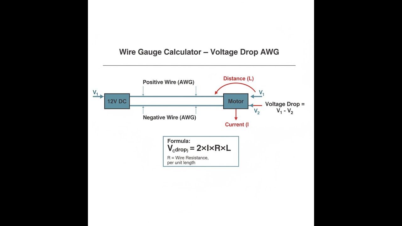
Wire Voltage Drop Diagram

Wire Gauge Voltage Drop Calculator
How to Use This Calculator
- Enter the current your load draws in the Current (Amps) field.
- Enter the one-way wire run length in the Distance (Feet) field, then enter your supply voltage in Source Voltage (V).
- Set your acceptable loss threshold in the Max Voltage Drop (%) field — 3% is the recommended starting point for motors and actuators.
- Click Calculate to see your result.
Wire Gauge Voltage Drop Interactive Visualizer
See how current, distance, and wire gauge affect voltage drop in real-time. Watch the voltage loss visualization change as you adjust parameters to find the optimal AWG wire size for your actuator installation.
VOLTAGE DROP
0.64V
DROP PERCENTAGE
5.3%
LOAD VOLTAGE
11.36V
FIRGELLI Automations — Interactive Engineering Calculators
Voltage Drop Equations
Primary Voltage Drop Formula
Use the formula below to calculate voltage drop across a wire run.
Note: The factor of 2 accounts for the round-trip path through both positive and negative conductors.
Related Calculations
Drop % = (Vdrop ÷ Vsource) × 100
Vload = Vsource - Vdrop
Simple Example
A 12V actuator draws 10A and is located 20 feet from the power supply. Using 12 AWG wire (R = 0.001588 Ω/ft):
- Vdrop = 2 × 10 × 0.001588 × 20 = 0.635V
- Drop % = (0.635 ÷ 12) × 100 = 5.3% — exceeds the 3% limit
- Upgrade to 10 AWG: Vdrop = 2 × 10 × 0.0009989 × 20 = 0.40V (3.3%) — acceptable
Understanding Wire Gauge and Voltage Drop
What is Voltage Drop?
Voltage drop is the reduction in electrical potential that occurs when current flows through a conductor's resistance. Every wire has inherent resistance that increases with length and decreases with cross-sectional area. When electrical current flows through this resistance, some voltage is "lost" as heat, reducing the voltage available at the load.
For electric motors and actuators, this phenomenon is particularly critical because these devices are sensitive to voltage variations. A FIRGELLI linear actuator rated for 12V DC may experience reduced speed, torque, or even operational failure if the supplied voltage drops significantly below its design specification.
Why Wire Gauge Matters
The American Wire Gauge (AWG) system uses inverse numbering—smaller AWG numbers indicate larger wire diameters and lower resistance. For example, 12 AWG wire has approximately 63% more cross-sectional area than 14 AWG wire, resulting in correspondingly lower resistance per foot.
This wire gauge voltage drop calculator helps determine the optimal AWG size by calculating the resistance-induced voltage loss over a given distance. The goal is to select wire thick enough to keep voltage drop within acceptable limits while avoiding unnecessarily oversized (and expensive) conductors.
The Physics Behind Voltage Drop
Voltage drop follows Ohm's Law (V = I × R) combined with the physical properties of copper conductors. The resistance of a wire depends on four factors:
- Material resistivity: Copper has lower resistivity than aluminum
- Length: Resistance increases linearly with wire length
- Cross-sectional area: Larger diameter reduces resistance
- Temperature: Resistance increases with temperature
The formula Vdrop = 2 × I × R × L incorporates the "2" factor because current must complete a circuit through both positive and negative conductors, effectively doubling the resistance path.
Worked Example: Linear Actuator Installation
Consider installing a 12V linear actuator that draws 8 amps at full load, located 25 feet from the power supply. We want to limit voltage drop to 3% (0.36V).
Given:
- Current (I) = 8 amps
- Distance (L) = 25 feet
- Source voltage = 12V
- Maximum acceptable drop = 3% = 0.36V
Solution:
Testing different wire gauges:
- 14 AWG: R = 0.002525 Ω/ft, Vdrop = 2 × 8 × 0.002525 × 25 = 1.01V (8.4% - too high)
- 12 AWG: R = 0.001588 Ω/ft, Vdrop = 2 × 8 × 0.001588 × 25 = 0.635V (5.3% - still high)
- 10 AWG: R = 0.0009989 Ω/ft, Vdrop = 2 × 8 × 0.0009989 × 25 = 0.40V (3.3% - close)
- 8 AWG: R = 0.0006282 Ω/ft, Vdrop = 2 × 8 × 0.0006282 × 25 = 0.251V (2.1% - acceptable)
The calculation shows that 8 AWG wire is required to maintain voltage drop within 3%. Using inadequate wire size would result in the actuator receiving only 11.6V instead of the required 12V with 12 AWG wire.
Design Considerations and Best Practices
Voltage Drop Limits
Industry standards recommend different voltage drop limits based on application:
- Critical loads (motors, actuators): 2-3%
- General lighting: 3-5%
- Non-critical loads: Up to 5%
Temperature Derating
Wire resistance increases approximately 0.4% per degree Celsius above 20°C. In hot environments or bundled installations, consider using the next larger wire size to compensate for temperature-induced resistance increases.
Future Load Considerations
When sizing wire for actuator systems, consider potential future modifications or load increases. Installing slightly oversized wire initially can accommodate system expansions without rewiring.
Applications in Automation Systems
Proper wire sizing is essential for automated systems using multiple actuators. In applications like adjustable desks, medical equipment, or industrial machinery, consistent voltage delivery ensures synchronized operation and prevents premature wear.
For complex installations involving multiple FIRGELLI linear actuators, this wire gauge voltage drop calculator becomes invaluable for planning electrical distribution. Each actuator branch must be analyzed separately, considering its specific current draw and distance from the power source.
Economic Considerations
While larger wire costs more initially, the investment pays dividends through:
- Reduced energy losses (lower operating costs)
- Extended equipment life due to proper voltage supply
- Elimination of performance issues and service calls
- Compliance with electrical codes and safety standards
Safety and Code Compliance
Beyond performance considerations, proper wire sizing ensures compliance with National Electrical Code (NEC) requirements. The NEC mandates maximum voltage drop limits for different installation types, making this calculator an essential tool for code-compliant designs.
Additionally, undersized wire can create safety hazards through excessive heating, potentially leading to insulation degradation or fire risk. Always verify that your selected wire gauge meets both voltage drop requirements and current-carrying capacity (ampacity) requirements.
Advanced Considerations
For precision applications, consider additional factors that affect voltage drop calculations:
- AC vs DC systems: AC systems involve additional complexity due to impedance, skin effect, and power factor
- Wire material: Aluminum wire has higher resistance than copper and requires different sizing
- Conduit effects: Wire bundling in conduits can increase operating temperature and resistance
- Harmonic distortion: Non-linear loads can increase effective current beyond nameplate ratings
This comprehensive understanding of voltage drop principles enables engineers to design robust electrical systems that maintain optimal performance throughout their operational life. Whether working with simple single-actuator systems or complex automation networks, proper wire sizing forms the foundation of reliable electrical design.
Frequently Asked Questions
📐 Browse all 1000+ Interactive Calculators →
About the Author
Robbie Dickson
Chief Engineer & Founder, FIRGELLI Automations
Robbie Dickson brings over two decades of engineering expertise to FIRGELLI Automations. With a distinguished career at Rolls-Royce, BMW, and Ford, he has deep expertise in mechanical systems, actuator technology, and precision engineering.
🔗 Related Engineering Calculators
More related engineering calculators:
- Cable Sizing Calculator Current and Voltage Drop
- Voltage Divider Calculator
- Wire Ampacity Calculator Nec Table
- Voltage Divider Calculator Output Voltage From Two Resistors
- Voltage Divider ADC Resolution Calculator
- Power Supply Sizing Calculator
- Ohms Law Calculator V I R P
- PWM Duty Cycle Calculator Average Voltage
- Strain Gauge Bridge Output Voltage Calculator
- Motor Torque Calculator Hp Rpm Torque
- Wire Size Calculator — AWG, mm² & Voltage Drop for DC and AC Circuits
Browse all engineering calculators →
Need to implement these calculations?
Explore the precision-engineered motion control solutions used by top engineers.


