If you don't know the LC circuit's resonant frequency when you build it, your filter or oscillator will almost certainly miss its target. The calculator here gives you the frequency, required inductance or capacitance, Q, bandwidth, and series impedance for any combination of L, C, R, or frequency you enter. In areas like RF, wireless power, and medical imaging, getting LC resonance right is key. Below you'll find the working formulas, a detailed FM tuner example, practical theory, and common troubleshooting issues around parasitics, Q, and temperature effects.
What is LC Resonant Frequency?
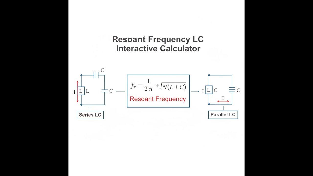
Resonant frequency in an LC circuit is simply the frequency where an inductor and capacitor exchange energy at their most efficient rate. At this point, their opposite reactive effects cancel each other, and the circuit's impedance does something useful—either dropping to a minimum in series or peaking in parallel. That's the frequency you want to design around if you're using LC resonance for filtering or generating signals.
Simple Explanation
Imagine a swing: if you push at exactly the right point in its arc, you keep it moving with almost no effort. An LC circuit is similar, with energy constantly shifting between the inductor's magnetic field and the capacitor's electric field. The resonant frequency is the natural pace of this energy exchange, and it's determined entirely by the values of L and C that you pick.
📐 Browse all 1000+ Interactive Calculators
LC Circuit Diagram

Resonant Frequency Calculator
How to Use This Calculator
This calculator is intended for education, concept evaluation, and preliminary design. Results are based on the equations and assumptions described on this page, but cannot account for every real-world load case, tolerance, material property, environmental condition, installation detail, safety factor, code, or regulatory requirement. Verify all inputs, assumptions, units, and results independently before selecting components or using the result in a real application. Safety-critical, structural, medical, lifting, transportation, or regulated applications must be reviewed by a qualified engineer.
- Pick what you want to solve for (frequency, L, C, impedance, Q, or bandwidth).
- Enter the values for L, C, R, or frequency as needed. Choose the right units.
- If you want to see a sample calculation, hit Try Example to auto-fill values.
- Click Calculate to get your answer.
LC Resonant Frequency Interactive Visualizer
Adjust the values to see for yourself how energy bounces between the inductor and capacitor. You’ll spot how changes in L or C shift the natural frequency, and how the reactances equal out at resonance.
FREQUENCY
232 kHz
QUALITY (Q)
23.0
REACTANCE
146 Ω
IMPEDANCE
10 Ω
FIRGELLI Automations — Interactive Engineering Calculators
Resonance Equations
Use the formula below to calculate resonant frequency from inductance and capacitance.
Fundamental Resonant Frequency
f0 = 1 / (2π√LC)
Where:
- f0 = Resonant frequency (Hz)
- L = Inductance (H)
- C = Capacitance (F)
- π = Mathematical constant (≈ 3.14159)
Angular Resonant Frequency
ω0 = 1 / √LC
Where:
- ω0 = Angular frequency (rad/s)
- f0 = ω0 / 2π
Reactances at Resonance
XL = 2πf0L = XC = 1 / (2πf0C)
Where:
- XL = Inductive reactance (Ω)
- XC = Capacitive reactance (Ω)
- At resonance: XL = XC (reactances cancel)
Quality Factor
Q = (1/R) √(L/C) = X0 / R = f0 / BW
Where:
- Q = Quality factor (dimensionless)
- R = Series resistance (Ω)
- X0 = Characteristic impedance = √(L/C)
- BW = Bandwidth at -3 dB points (Hz)
Series Circuit Impedance
Zseries = R + j(XL - XC)
At resonance: Zseries = R (minimum)
Parallel Circuit Impedance
Zparallel = (jωL) || (1/jωC)
At resonance: Zparallel = L/(CR) (maximum)
Simple Example
Given: L = 100 μH, C = 470 pF
Formula: f₀ = 1 / (2π√LC)
LC = 100×10⁻⁶ × 470×10⁻¹² = 4.7×10⁻¹⁴
√LC = 6.856×10⁻⁷
Result: f₀ = 1 / (2π × 6.856×10⁻⁷) ≈ 232.1 kHz
Theory & Practical Applications
Fundamental Physics of LC Resonance
In real circuits, energy moves back and forth between the inductor's magnetic field and the capacitor's electric field. If nothing else (no losses or resistance) is present, that exchange keeps cycling at a frequency set only by L and C. The resonant frequency formula comes from setting the inductor's reactance equal to the capacitor's reactance but in opposite directions; this is where the circuit's response either peaks or dips sharply, depending on the configuration. In a series LC, impedance bottoms out—limited only by any real resistance left in the circuit. In a parallel LC, impedance peaks out, which is the whole point in tank circuits or basic radio filters.
The textbooks usually ignore a practical problem: self-resonant frequency of the parts themselves. Real inductors always have a bit of stray capacitance from turn to turn; real capacitors have a few nanohenries of inductance from their leads. Each part, even before you solder it in, will flip its behavior at a certain frequency. Your design is only predictable when you’re well below those limits.
For example, use a 10 μH inductor with 2 pF stray capacitance at 300 MHz and your "inductor" actually acts like a capacitor—because you’re above its self-resonant point. Best practice: use components whose self-resonant frequency is at least a few times higher than your actual circuit operating frequency.
Quality Factor: The Measure of Selectivity
Q tells you how narrow and "sharp" the resonance is. Higher Q means tighter bandwidth, good for sorting out signals close together in frequency (radio receivers, for instance). Lower Q gives you broad bandwidth, useful where you want the resonance to cover a wider range. Q boils down to keeping losses—mostly series resistance—low. That's why serious RF inductors use thick or even silver-plated wire, and good capacitors use very low-loss dielectrics. If you don't bother with Q or use parts with poor temperature stability, your resonance can drift or broaden out, making your circuit unreliable—especially above a few MHz, where even the PCB layout resistance starts to matter.
Series vs. Parallel Resonance: Dual Personalities
Series LC circuits reach minimum impedance at resonance—they become a low resistance path, shorting out the frequency they're tuned to. Watch out: the voltage across the capacitor or inductor isn't just the supply voltage—it's multiplied by Q. So with Q=50 and a 12V input, you get 600V across a component. That’s an easy way to fry parts accidentally.
Parallel LC circuits, on the other hand, hit maximum impedance at resonance, acting like an open circuit for that frequency. This makes them useful for filtering and for oscillator tanks. Again, real losses mean the "infinite" impedance isn’t achieved, but a well-designed tank can easily be a few kΩ at RF. Filters and oscillators rely on this property to work reliably.
Applications Across Engineering Disciplines
LC resonant circuits show up everywhere: in radios for channel selection, in induction heating equipment, and even in MRI scanners. Radios might use a dozen different LC circuits just for one receiver, each carefully set for the required bandwidth and Q. Induction heating uses LC to minimize the power wasted in the supply and maximize what's delivered to the load. For MRI machines, massive tunable LC tanks are adjusted to a specific frequency for imaging, and they must remain stable even as the patient or the environment varies.
Wireless power relies on loosely-coupled LC pairs, with both transmitter and receiver precisely matched in frequency. This is the only way to get efficient power transfer at short distances, and in real systems, the resonant frequency may need to track drift or environmental changes, sometimes on the fly using switchable capacitors.
Worked Example: FM Radio Antenna Tuner Design
Suppose you're tasked with building a variable LC for an FM radio covering 87.5–108 MHz, and need reasonable selectivity to avoid interference from adjacent 200 kHz-spaced channels.
Step 1: Start Mid-Band
Pick a usable variable cap: 8–45 pF is a standard range. At mid-band (f₀ = 97.75 MHz, C = 25 pF), calculate L with the resonance formula:
L = 1 / [(2πf₀)² × C] = 118 nH
Step 2: Check Tuning Range
Using 8 pF: f = 173 MHz (easily covers the high end). Using 45 pF: f = 73.1 MHz (covers the low end). If this range is too wide, tweak the cap range as shown; C = 15–30 pF yields about 89–127 MHz, so using a 118 nH inductor works just fine.
Step 3: Check Q for Selectivity
Bandwidth should be ≤100 kHz for 200 kHz channel separation, so Q ≈ 98 MHz / 0.1 MHz = 980, which is unrealistic for a single LC. Most front-ends settle for Q around 50–100, accepting more overlap and using downstream ceramic IF filters for better channel separation. With Q=80 and an impedance of 72 Ω, you get a max series resistance of under 1 Ω. Standard air-core inductors and C0G/NPO caps meet this.
Step 4: Parts and Parasitics
6 turns of 18 AWG wire on an 8mm diameter form will get you in the ballpark for 118 nH. Self-resonant frequency dominated by about 0.8 pF of stray capacitance puts the SRF around 430 MHz, which is nicely above the range of interest. A decent variable cap (silver-mica or NPO ceramic) keeps Q high; in most cases, the inductor is the main loss source. You'll end up with about 1 MHz of bandwidth—not surgically sharp, but good enough for FM with IF filtering down the line.
Step 5: Temperature Drift
Assume +30 ppm/°C for air-core L, -30 ppm/°C for NPO C; the drifts will mostly cancel. Real drift, after all contributions, will be around ±5 ppm/°C—about ±500 Hz for a 98 MHz center frequency. FM radios use AFC anyway, so this is well within practical requirements.
For other calculations or more detailed resonant circuit design, you can refer to the engineering calculator library.
Frequently Asked Questions
Free Engineering Calculators
Explore our complete library of free engineering and physics calculators.
Browse All Calculators →🔗 Explore More Free Engineering Calculators
- Wheatstone Bridge Calculator
- Resistor Color Code Calculator
- Capacitor Charge Discharge Calculator — RC Circuit
- Low-Pass RC Filter Calculator — Cutoff Frequency
- Capacitive Transformerless Power Supply Calculator
- Joule Heating Calculator
- Cutoff Frequency Calculator
- Voltage Divider Calculator
- Voltage Divider & ADC Resolution Calculator
- Transformer Turns Ratio Calculator
About the Author
Robbie Dickson — Chief Engineer & Founder, FIRGELLI Automations
Robbie Dickson brings over two decades of engineering expertise to FIRGELLI Automations. With a distinguished career at Rolls-Royce, BMW, and Ford, he has deep expertise in mechanical systems, actuator technology, and precision engineering.
Video Walkthrough - How to Use This Calculator
Need to implement these calculations?
Explore the precision-engineered motion control solutions used by top engineers.


