Determining safe working distances and adequate shielding around radioactive sources is a non-negotiable engineering problem — get it wrong and the consequences range from regulatory penalties to irreversible biological harm. Use this Radiation Exposure Distance Shielding Calculator to calculate dose rates at varying distances and through shielding materials using inverse square law principles, exponential attenuation equations, and your source activity inputs. It's critical in nuclear medicine, industrial radiography, and nuclear power plant maintenance planning. This page includes the governing formulas, a worked example, full engineering theory, and an FAQ covering practical compliance scenarios.
What is radiation exposure distance shielding?
Radiation exposure distance shielding refers to the combined use of physical distance and barrier materials to reduce the dose rate a person receives from a radioactive source. The farther you stand from a source — or the more shielding material between you and it — the lower your radiation exposure.
Simple Explanation
Think of a bonfire: the closer you stand, the hotter it feels. Move twice as far away and the heat drops dramatically — not by half, but by a factor of four. Radiation works the same way through distance. Add a barrier — like a lead wall — and you absorb even more of that energy before it reaches you, the same way a fireproof screen blocks radiant heat.
📐 Browse all 1000+ Interactive Calculators
Radiation Shielding Diagram

Radiation Exposure Distance Shielding Calculator
How to Use This Calculator
- Select your Calculation Mode from the dropdown — choose from dose at distance, safe distance, shielded dose, required thickness, maximum exposure time, or source activity.
- Enter the relevant input values for your selected mode — such as initial dose rate (mSv/h), distance (m), attenuation coefficient (cm⁻¹), or shield thickness (cm).
- Use the Try Example button to pre-fill values for the current mode if you want to see a working demonstration first.
- Click Calculate to see your result.
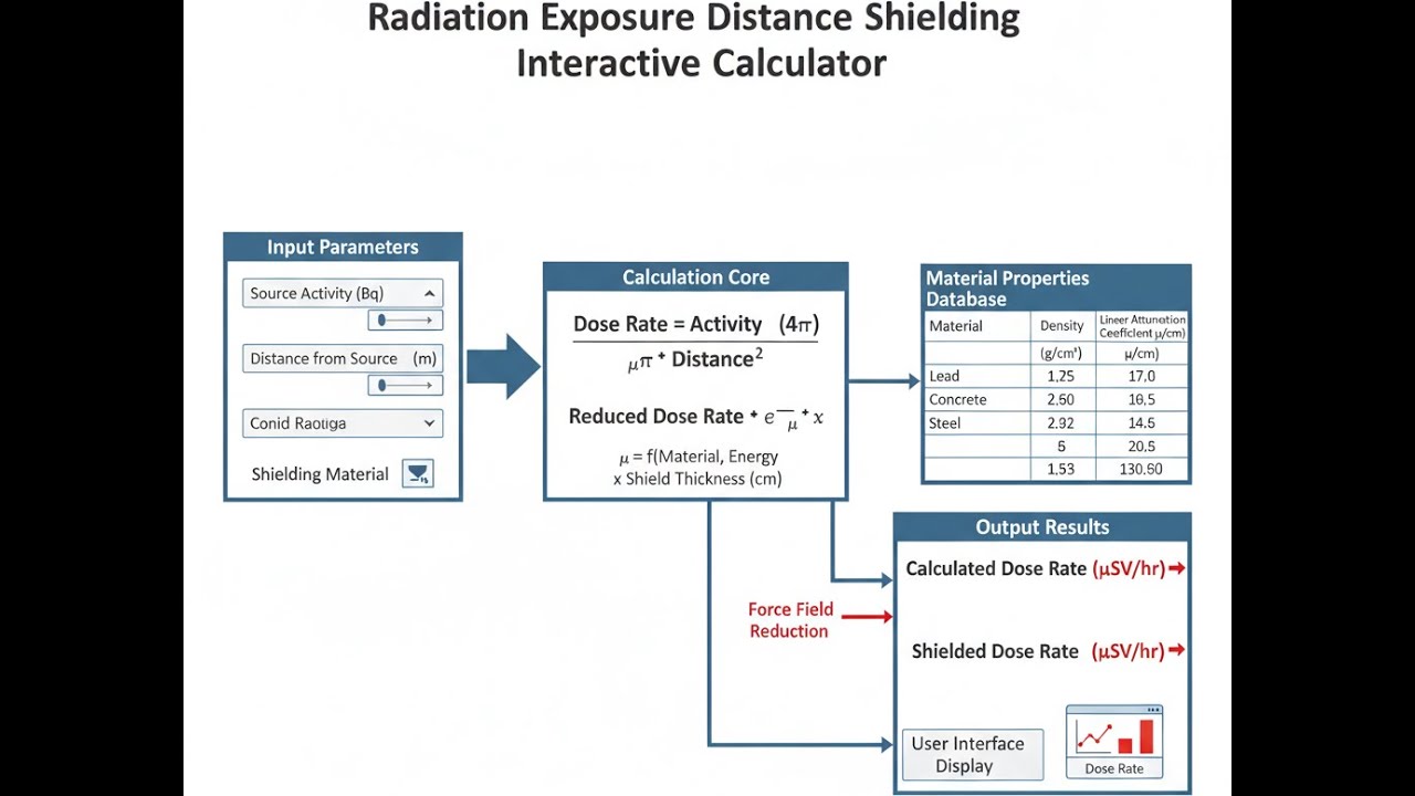
Radiation Exposure Distance Shielding Interactive Calculator
Visualize how distance and shielding materials reduce radiation dose rates using inverse square law and exponential attenuation principles. Adjust source activity, distance, and shield thickness to see real-time safety calculations for nuclear engineering applications.
DOSE RATE
4.8 mSv/h
REDUCTION
96.2%
SAFETY STATUS
MODERATE
FIRGELLI Automations — Interactive Engineering Calculators
Governing Equations
Use the formula below to calculate dose rate at a new distance using the inverse square law.
Inverse Square Law
D2 = D1 × (r1 / r2)2
Where:
- D1 = Initial dose rate at distance r1 (mSv/h)
- D2 = Dose rate at new distance r2 (mSv/h)
- r1 = Initial distance from source (m)
- r2 = New distance from source (m)
Use the formula below to calculate the transmitted dose rate through a shielding material.
Exponential Attenuation Law
D = D0 × e-μx
Where:
- D = Transmitted dose rate through shield (mSv/h)
- D0 = Incident dose rate before shielding (mSv/h)
- μ = Linear attenuation coefficient (cm-1)
- x = Shield thickness (cm)
Use the formula below to calculate half-value layer and tenth-value layer from the attenuation coefficient.
Half-Value Layer and Tenth-Value Layer
HVL = 0.693 / μ
TVL = 2.303 / μ
Where:
- HVL = Half-value layer thickness that reduces intensity by 50% (cm)
- TVL = Tenth-value layer thickness that reduces intensity by 90% (cm)
- μ = Linear attenuation coefficient (cm-1)
Use the formula below to calculate the required shield thickness to achieve a target dose rate.
Required Shield Thickness
x = ln(D0 / Dtarget) / μ
Where:
- x = Required shield thickness (cm)
- D0 = Unshielded dose rate (mSv/h)
- Dtarget = Desired dose rate after shielding (mSv/h)
- μ = Linear attenuation coefficient of shield material (cm-1)
Use the formula below to calculate maximum allowable exposure time from a dose rate and dose limit.
Maximum Exposure Time
t = Dlimit / Ḋ
Where:
- t = Maximum allowable exposure time (h)
- Dlimit = Regulatory dose limit (mSv)
- Ḋ = Dose rate at work location (mSv/h)
Simple Example
Scenario: A source produces 50 mSv/h at 1 m. What is the dose rate at 5 m?
- Initial dose rate (D1): 50 mSv/h
- Initial distance (r1): 1 m
- New distance (r2): 5 m
- D2 = 50 × (1/5)² = 50 × 0.04 = 2.0 mSv/h
Moving 5 times farther away cuts the dose rate by a factor of 25 — from 50 mSv/h down to 2.0 mSv/h.
Theory & Engineering Applications
Fundamental Radiation Interaction Physics
Radiation exposure follows predictable physical laws governing energy transport through space and matter. The inverse square law describes how radiation intensity from a point source decreases with the square of the distance traveled, a consequence of geometric spreading across an expanding spherical wavefront. For a source emitting radiation uniformly in all directions, the intensity at any point equals the total emission divided by the surface area of a sphere (4πr²) at that radius. This relationship applies strictly to point sources in vacuum or air, where scattering and attenuation are negligible compared to geometric dilution effects.
When radiation traverses material shields, photons undergo three primary interaction mechanisms depending on energy: photoelectric absorption dominates below 100 keV, Compton scattering prevails from 100 keV to 3 MeV, and pair production becomes significant above 1.02 MeV. The linear attenuation coefficient μ quantifies the probability of interaction per unit path length, representing the combined effects of all interaction processes. This coefficient varies dramatically with photon energy and shield atomic number—lead (Z=82) provides superior shielding for diagnostic X-rays (30-150 keV) with μ ≈ 5.2 cm⁻¹ at 100 keV, while concrete (effective Z ≈ 11) requires significantly greater thickness but offers practical advantages for large-scale installations.
Build-Up Factor Corrections for Real-World Shielding
The exponential attenuation equation D = D₀e⁻ᵘˣ accurately describes narrow-beam geometry where all scattered photons are excluded from detection. However, practical shielding scenarios involve broad-beam conditions where photons scattered within the shield contribute additional dose beyond the attenuated primary beam. Build-up factor B(μx,E) quantifies this enhancement, with the complete expression becoming D = D₀ B(μx,E) e⁻ᵘˣ. For cobalt-60 gamma rays (1.17 and 1.33 MeV average) through concrete, build-up factors reach 2.5 at 5 mean free paths, effectively halving the shielding effectiveness predicted by simple exponential decay. Engineers designing vault shielding for linear accelerators or radiotherapy facilities must incorporate energy-dependent build-up data, typically adding 15-30% additional thickness to conservative calculations.
Point kernel integration methods provide more rigorous treatment of distributed sources with complex geometries. These techniques subdivide extended sources into differential volume elements, calculate contributions from each element including attenuation and build-up along the path to the dose point, then integrate across the entire source distribution. Modern Monte Carlo radiation transport codes (MCNP, GEANT4, FLUKA) simulate individual particle histories through detailed geometric models, inherently accounting for scatter, secondary particle generation, and energy deposition with statistical precision approaching 1-2% uncertainty after sufficient computational sampling.
Distance Optimization in Radiation Work Planning
The ALARA principle (As Low As Reasonably Achievable) mandates minimizing exposures through optimization of time, distance, and shielding. Distance provides the most cost-effective dose reduction for many industrial radiography and nuclear medicine procedures. Doubling the distance from a source reduces dose by a factor of four, while tripling distance achieves a nine-fold reduction without requiring additional equipment or materials. Remote handling tools, telescopic manipulators, and robotic systems enable operators to maintain 2-5 meter standoff distances from high-activity sources during industrial gamma radiography using iridium-192 (typical activity 2-4 TBq) or cobalt-60 industrial sources.
Practical distance calculations must account for facility geometry constraints and scattered radiation contributions. In confined spaces such as piping inspection scenarios, operators cannot always achieve theoretical optimal distances. Collimation reduces scatter by restricting the primary beam solid angle, while backscatter from structural elements behind the source can increase dose rates by 20-40% compared to free-field conditions. Dose rate surveys using calibrated ion chambers or energy-compensated Geiger-Müller detectors establish actual exposure gradients, revealing hotspots from duct streaming, inadequate joint shielding, or unexpected reflection geometries that violate inverse square predictions.
Material-Specific Attenuation Properties
Lead remains the standard shielding material for medical and industrial X-ray applications due to its high density (11.34 g/cm³) and atomic number (82), providing mass attenuation coefficients 3-5 times greater than iron or concrete for energies below 500 keV. A half-value layer for 100 keV photons in lead measures approximately 0.027 cm compared to 1.66 cm in concrete—a 60-fold advantage in thickness reduction. However, lead becomes less advantageous at higher energies where Compton scattering dominates: at 2 MeV, lead's HVL advantage over concrete decreases to roughly 5-fold. Economic considerations often favor concrete for accelerator vaults and spent fuel storage, where wall thicknesses of 1.5-3 meters provide adequate shielding at acceptable construction costs.
Water serves as effective neutron shielding through elastic scattering with hydrogen nuclei, rapidly thermalizing fast neutrons from fission or accelerator sources. Polyethylene and borated polyethylene composites offer portable neutron shielding, with the latter incorporating boron-10 to capture thermalized neutrons via the ¹⁰B(n,α)⁷Li reaction. Tungsten alloys (density 17-19 g/cm³) provide superior shielding per unit volume for applications demanding minimal thickness, such as radiotherapy collimators and industrial radiography cameras, despite costs 10-20 times higher than lead. Depleted uranium (density 19.1 g/cm³) offers the ultimate compact shielding but faces regulatory restrictions and handling concerns regarding its pyrophoric and toxic properties.
Regulatory Dose Limits and Compliance Calculations
The International Commission on Radiological Protection (ICRP) Publication 103 establishes the current framework for occupational exposure limits: 20 mSv per year averaged over five consecutive years with no single year exceeding 50 mSv, plus a lens of eye limit of 20 mSv annually. Public exposure limits restrict doses to 1 mSv per year excluding natural background and medical exposures. Nuclear Regulatory Commission (NRC) 10 CFR Part 20 implements similar limits in the United States, defining restricted areas where dose rates could exceed 0.05 mSv in one hour, requiring controlled access, posting, and personnel monitoring.
Dose rate calculations determine required posting categories and access controls. Areas where personnel could receive 1 mSv in one hour (1000 μSv/h) require high radiation area designation with alarmed access controls. Very high radiation areas (500 rad or 5 Gy in one hour at 1 meter) demand additional administrative controls including direct surveillance or locked barriers. Typical nuclear power plant radiological work permits calculate integrated dose projections by multiplying measured dose rates by estimated stay times, incorporating contingency factors of 1.5-2.0 to account for task complications, with pre-job briefings establishing turn-back dose limits typically set at 75% of planned exposure.
Worked Example: Shielded Distance Calculation for Industrial Radiography
Problem Statement: An industrial radiography team uses a 3.7 TBq (100 Ci) iridium-192 source for weld inspection. The gamma constant for Ir-192 is 0.485 mSv·m²·GBq⁻¹·h⁻¹. They need to establish a controlled area boundary where the dose rate does not exceed 0.02 mSv/h (20 μSv/h). The source is positioned behind a 3 cm steel plate (μ = 0.462 cm⁻¹ for Ir-192's average 0.38 MeV gamma energy). Calculate: (a) the unshielded dose rate at 5 meters, (b) the shielded dose rate at 5 meters, and (c) the minimum distance required to achieve 0.02 mSv/h with the steel shielding in place.
Solution Part (a) - Unshielded Dose Rate:
The dose rate at distance r from a point source is given by:
Ḋ = Γ × A / r²
Where Γ = 0.485 mSv·m²·GBq⁻¹·h⁻¹, A = 3700 GBq (converting from 3.7 TBq), and r = 5 m.
Ḋ = (0.485 × 3700) / 5²
Ḋ = 1794.5 / 25
Ḋ = 71.78 mSv/h
This extremely high unshielded dose rate would deliver the annual occupational limit in approximately 16.7 minutes, demonstrating the necessity of both shielding and distance controls.
Solution Part (b) - Shielded Dose Rate at 5 Meters:
First calculate the transmission factor through 3 cm of steel using exponential attenuation:
T = e⁻ᵘˣ = e⁻⁽⁰·⁴⁶²⁾⁽³⁾
T = e⁻¹·³⁸⁶
T = 0.250
The steel reduces intensity by 75%, transmitting 25% of the incident radiation. The shielded dose rate at 5 meters becomes:
Ḋshielded = 71.78 × 0.250 = 17.95 mSv/h
This represents a reduction from 71.78 to 17.95 mSv/h, still far exceeding safe levels for unrestricted access. The steel shielding provides 1.85 half-value layers (HVL = 0.693/0.462 = 1.50 cm), reducing dose by a factor of approximately 3.6.
Solution Part (c) - Minimum Distance for 0.02 mSv/h Target:
We need to find the distance where the shielded dose equals 0.02 mSv/h. Using the inverse square relationship:
Ḋtarget = (Γ × A × T) / r²
Rearranging for distance r:
r = √[(Γ × A × T) / Ḋtarget]
r = √[(0.485 × 3700 × 0.250) / 0.02]
r = √[448.625 / 0.02]
r = √22,431.25
r = 149.8 meters
The controlled area boundary must be established at approximately 150 meters radius to achieve the target dose rate of 0.02 mSv/h with the 3 cm steel shielding. Without the steel barrier, this distance would increase to 299.5 meters (calculated as 149.8 / √0.250), demonstrating how combining shielding with distance optimization reduces the required exclusion zone by a factor of 2. In practice, radiographers would deploy additional directional shielding, use collimation to restrict the beam geometry, and implement administrative controls including barricades, signage, and dedicated safety observers to prevent unauthorized access to high-dose areas closer to the source.
This calculation assumes negligible scatter and build-up, appropriate for initial safety planning. Field measurements using survey instruments would verify actual dose rates, with typical build-up factors for steel potentially increasing the calculated 17.95 mSv/h by 10-20% depending on geometric configuration and surrounding materials. For more comprehensive resources on radiation safety calculations and engineering tools, visit our complete calculator library.
Practical Applications
Scenario: Hospital Radiation Safety Officer Designing PET-CT Suite Shielding
Dr. Jennifer Martinez, radiation safety officer at a regional cancer center, must design shielding for a new PET-CT facility housing a fluorine-18 FDG synthesis module and imaging suite. The cyclotron-produced F-18 arrives weekly at 370 GBq activity, decaying with a 110-minute half-life while stored in a hot cell before patient dose preparation. Using the calculator's shielded dose mode with lead's attenuation coefficient of 0.77 cm⁻¹ for 511 keV annihilation photons, she determines that 4.5 cm of lead brick (3 HVLs at 0.90 cm each) reduces the 92 mSv/h surface dose from the storage vial to 11.5 mSv/h—still requiring restricted access. Adding distance calculations, she establishes a 2.5-meter minimum approach boundary where technicians preparing doses would receive 1.84 mSv/h, allowing 10-minute maximum occupancy periods per regulatory limits. The combined shielding and distance strategy reduces technician doses by 98.7% compared to unshielded contact scenarios, enabling safe radiopharmacy operations while maintaining efficient patient scheduling for the 12-15 daily PET scans. Her calculations justify the $47,000 shielding installation cost by demonstrating ALARA compliance and eliminating the need for robotic dose dispensing equipment that would have cost $180,000.
Scenario: Pipeline Inspector Calculating Safe Standoff During Gamma Radiography
Marcus Chen, a certified industrial radiographer with 12 years' experience, inspects welds on a 36-inch natural gas transmission pipeline using a 2.96 TBq (80 Ci) iridium-192 source in a 660B exposure device. Working in a rural area at night to minimize public exposure, he uses the safe distance calculation mode to determine that his survey boundary must extend 127 meters to achieve the 0.02 mSv/h unrestricted area limit. His two-person crew establishes this perimeter using reflective barriers and warning lights, then positions the source using a 20-meter guide tube that allows him to maintain 25 meters minimum distance during the 4-minute exposures. At this distance, the calculator shows his dose rate drops to 1.82 mSv/h, and the maximum exposure time mode indicates he can safely perform 8 exposures (32 minutes total beam-on time) before reaching his company's conservative 50 mSv per job administrative limit—well below the 0.25 mSv he actually receives during the job. The calculations prove critical when a motorist approaches the barrier at 2 AM; Marcus immediately retrieves the source using the emergency crank, and his documented safe distance calculations demonstrate regulatory compliance during the subsequent incident investigation, avoiding the $75,000 citation issued to another company whose insufficient boundary allowed public exposure.
Scenario: Nuclear Power Plant ALARA Coordinator Planning Valve Maintenance
Sarah Kowalski, ALARA coordinator at a 1200 MWe pressurized water reactor, plans maintenance on a containment isolation valve with deposited cobalt-60 creating a 35 mSv/h contact dose rate on the valve body surface. The four-hour valve repacking job requires workers to maintain hand contact with the valve for torque wrench operations, making distance controls impractical. Using the required shielding thickness calculator mode with lead wool's attenuation coefficient of 1.23 cm⁻¹ for Co-60's 1.17-1.33 MeV gammas, she calculates that 3.8 cm of lead blanket shielding (6.7 HVLs) will reduce the dose to 0.28 mSv/h at the work surface. She then uses the exposure time calculator to determine that each technician can work 71 minutes before reaching the 0.2 mSv per-job administrative limit, requiring a six-person rotation to complete the task. Her detailed shielding plan, backed by calculator-verified dose projections, reduces the collective crew dose from a projected 140 person-mSv (unshielded scenario) to 1.2 person-mSv—a 99.1% reduction that saves the utility approximately $420,000 in avoided dose costs at their $3,000 per person-mSv internal accounting value, while the custom lead blankets cost only $8,500 to fabricate and will be reused for similar jobs throughout the outage.
Frequently Asked Questions
Why does the inverse square law only apply to point sources, and when does it break down in practical situations? +
How do I select the correct attenuation coefficient when dealing with polyenergetic sources or multiple shielding layers? +
What safety factors should I apply to calculated shielding requirements for regulatory compliance? +
How do I account for scattered radiation and skyshine when establishing radiation area boundaries outdoors? +
What are the practical differences between using lead versus tungsten for portable shielding applications? +
How do I calculate effective dose from dose rate measurements for compliance with annual exposure limits? +
Free Engineering Calculators
Explore our complete library of free engineering and physics calculators.
Browse All Calculators →🔗 Explore More Free Engineering Calculators
About the Author
Robbie Dickson — Chief Engineer & Founder, FIRGELLI Automations
Robbie Dickson brings over two decades of engineering expertise to FIRGELLI Automations. With a distinguished career at Rolls-Royce, BMW, and Ford, he has deep expertise in mechanical systems, actuator technology, and precision engineering.
Need to implement these calculations?
Explore the precision-engineered motion control solutions used by top engineers.


