Designing high-frequency circuits or specifying conductors for switching power supplies means skin effect isn't optional — it's the dominant loss mechanism you must size for. Use this Skin Depth Interactive Calculator to calculate skin depth, AC resistance ratio, effective conducting area, and related parameters using frequency, conductivity, relative permeability, and wire radius. It matters across RF shielding design, PCB trace engineering for GHz signals, and power electronics running at tens or hundreds of kilohertz. This page includes the full formula, a worked inductor design example, plain-English theory, and a practical FAQ.
What is skin depth?
Skin depth is the distance from the surface of a conductor at which the current density falls to about 37% of its surface value. The higher the frequency, the shallower this depth — meaning AC current crowds toward the outer surface of any conductor.
Simple Explanation
Think of a copper wire carrying AC as a pipe where water only flows through a thin outer ring — the center is mostly unused. At low frequencies, most of the wire carries current. At high frequencies, only a thin skin at the surface does the work. That's why fat solid wires at radio frequencies behave like much thinner ones electrically — and why litz wire (many fine strands) solves the problem.
📐 Browse all 1000+ Interactive Calculators
Skin Depth Visualization

Skin Depth Calculator
How to Use This Calculator
- Select your calculation mode from the dropdown — choose skin depth, frequency, conductivity, permeability, AC resistance ratio, or effective conducting area.
- Enter the material properties: conductivity (S/m) and relative permeability. Use the reference values shown below the conductivity field as a starting point.
- Enter frequency (Hz) and, where required, wire radius (m) for the geometry you are analyzing.
- Click Calculate to see your result.
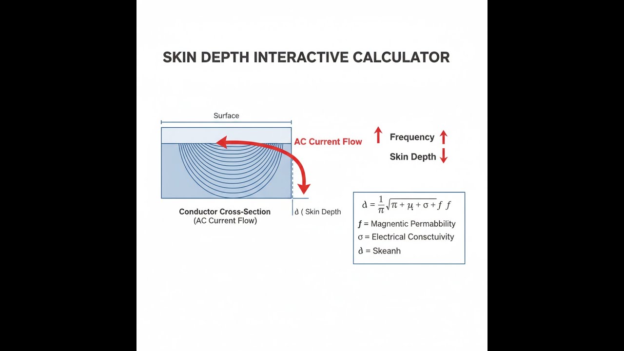
Skin Depth Interactive Visualizer
Watch how AC current density decays exponentially with depth as frequency increases. Adjust frequency, conductivity, and permeability to see how skin depth changes and affects AC resistance in real-time.
SKIN DEPTH
65.4 μm
AC/DC RATIO
7.65×
EFF. AREA
13.1%
FIRGELLI Automations — Interactive Engineering Calculators
Fundamental Equations
Use the formula below to calculate skin depth from frequency, conductivity, and permeability.
Skin Depth (Classical Formula)
δ = √(2 / (ω μ σ)) = √(1 / (π f μ σ))
Where:
- δ = skin depth (m) — depth at which current density falls to 1/e of surface value
- ω = angular frequency = 2πf (rad/s)
- f = frequency (Hz)
- μ = absolute permeability = μrμ0 (H/m)
- μr = relative permeability (dimensionless, ~1 for non-magnetic materials)
- μ0 = permeability of free space = 4π × 10-7 H/m
- σ = electrical conductivity (S/m or Ω-1m-1)
Current Density Decay
J(x) = J0 e-x/δ
Where:
- J(x) = current density at depth x (A/m²)
- J0 = surface current density (A/m²)
- x = depth from surface (m)
- e = Euler's number ≈ 2.71828
Note: At x = δ, current density drops to ~37%; at x = 3δ, only ~5% remains; at x = 5δ, less than 1%.
AC Resistance Ratio (Cylindrical Conductor)
RAC / RDC ≈ (r / 2δ) for r >> δ
Where:
- RAC = AC resistance at frequency f (Ω)
- RDC = DC resistance (Ω)
- r = conductor radius (m)
Approximation valid when wire radius greatly exceeds skin depth. For precise calculations, use Bessel function solutions.
Surface Impedance
Zs = (1 + j) / (σ δ) = √(j ω μ / σ)
Where:
- Zs = surface impedance (Ω)
- j = imaginary unit (√-1)
- Real and imaginary parts equal: Rs = Xs = 1/(σδ)
Simple Example
Copper wire at 1 MHz. σ = 5.96 × 10⁷ S/m, μr = 1, f = 1,000,000 Hz.
δ = √(1 / (π × 1×10⁶ × 1.257×10⁻⁶ × 5.96×10⁷)) = √(1 / 2.355×10⁸) ≈ 65 μm (0.065 mm).
A 1 mm diameter copper wire at 1 MHz has r/δ ≈ 7.7 — strong skin effect. AC resistance is roughly 3.8× its DC value.
Theory & Practical Applications
Physical Mechanism of the Skin Effect
The skin effect arises from electromagnetic induction within conductors carrying alternating current. When AC flows through a conductor, it generates a time-varying magnetic field that induces eddy currents according to Faraday's law. These eddy currents oppose the original current in the conductor's interior (by Lenz's law) but reinforce it near the surface. The result is an exponential decay of current density with depth, characterized by the skin depth δ. This phenomenon is fundamentally a consequence of Maxwell's equations applied to conducting media and becomes increasingly pronounced at higher frequencies.
The exponential decay follows J(x) = J₀ exp(-x/δ), where the characteristic length δ depends on the conductor's electromagnetic properties and the frequency of excitation. At depth δ, current density has fallen to approximately 37% (1/e) of its surface value. At 3δ, only 5% remains, and practical engineering analysis often considers current effectively zero beyond 3-5 skin depths. This concentrated current distribution increases the effective resistance of the conductor because current flows through a reduced cross-sectional area, generating higher I²R losses than DC current distributed uniformly across the entire conductor cross-section.
Material Dependencies and Non-Obvious Behavior
While the classical skin depth formula δ = √(2/(ωμσ)) suggests straightforward scaling with material properties, real-world behavior exhibits subtleties that catch inexperienced engineers. Copper's conductivity of 5.96 × 10⁷ S/m is commonly cited, but this value applies only at 20°C — conductivity decreases approximately 0.4% per °C above this temperature. A copper bus bar operating at 70°C has roughly 20% higher resistivity than handbook values suggest, significantly reducing skin depth and increasing AC resistance at elevated temperatures. Temperature-dependent calculations become essential for high-current applications where self-heating is substantial.
Ferromagnetic materials introduce frequency-dependent permeability that violates the simple √f scaling. At low frequencies, silicon steel may exhibit μr = 4000, but as frequency increases into the kilohertz range, domain wall motion cannot track the rapidly changing field, and effective permeability drops dramatically — sometimes by an order of magnitude. This creates a situation where skin depth decreases less rapidly with frequency than the √f relationship predicts. Engineers designing magnetic components for switching power supplies (50-500 kHz) cannot simply extrapolate low-frequency permeability values; they must consult manufacturer frequency response data or measure complex permeability directly.
High-Frequency Circuit Design Implications
In RF and microwave engineering, skin effect dominates conductor loss mechanisms. At 1 GHz in copper, skin depth shrinks to approximately 2.1 micrometers — thinner than typical electroplating thickness. PCB trace design at these frequencies must account for surface roughness effects: the RMS roughness of standard copper cladding (1-3 μm) becomes comparable to skin depth, causing current to travel a longer path over surface asperities. This "roughness loss" can double the predicted conductor loss at millimeter-wave frequencies. High-performance PCBs for 5G and radar applications specify reverse-treated foil (RTF) with ≤0.5 μm roughness to minimize this effect.
Coaxial cable design at microwave frequencies involves careful optimization of inner and outer conductor dimensions relative to skin depth. A solid inner conductor of radius much greater than δ wastes material and mass without improving performance — current flows only in the outermost skin depth regardless of total radius. This drives the use of hollow tubular inner conductors in high-power waveguide systems, where a thick-wall tube provides necessary mechanical rigidity while minimizing weight and material cost. However, the wall thickness must exceed 3-5 skin depths to prevent current penetration through the wall, which would radiate energy and compromise shielding.
Power System and Motor Design Applications
In large power transformers and motors, skin effect at 50/60 Hz appears negligible given that δ exceeds 9 mm in copper. However, transient phenomena and harmonic content change the picture substantially. Variable frequency drives (VFDs) supplying motors inject significant harmonics — 5th, 7th, 11th, and 13th harmonics are common in six-pulse drives. The 11th harmonic of a 60 Hz fundamental sits at 660 Hz, where skin depth has decreased by √11 ≈ 3.3× compared to the fundamental. Motor windings carrying this harmonic content experience resistance increases of 50-100% beyond DC values, generating additional heat and reducing efficiency by several percentage points. Modern motor designs for VFD applications specify distributed winding patterns or parallel strands to mitigate this loss.
Busbar design in electrical substations and industrial facilities must consider fault current skin effect, not just nominal frequency operation. A short-circuit fault can inject transient currents with spectral content extending to several kilohertz. During the first few cycles of a fault, the effective resistance of aluminum or copper busbars rises substantially due to skin effect at these transient frequencies, affecting arc flash calculations and protection coordination. Conservative designs assume 50-100% higher resistance than DC values when calculating fault current magnitudes and durations.
Shielding Effectiveness and EMC Design
Electromagnetic shielding relies fundamentally on skin effect to attenuate incident electromagnetic fields. A conductive enclosure must have wall thickness of at least 3-5 skin depths to provide effective shielding. At 100 kHz, aluminum (σ = 3.77 × 10⁷ S/m) exhibits δ ≈ 260 μm, requiring minimum wall thickness of 0.8-1.3 mm. Standard 1/16" (1.6 mm) aluminum sheet provides adequate shielding at this frequency. However, at 1 MHz where δ drops to 82 μm, even thin aluminum foil (50 μm) provides marginal shielding — the field penetrates partially through the shield.
Engineers frequently encounter the misconception that any continuous metal enclosure provides "complete" shielding. In reality, shielding effectiveness (SE) depends critically on shield thickness relative to skin depth: SE ≈ 20 log₁₀(e^(t/δ)) dB for t >> δ, where t is wall thickness. A shield of thickness 3δ provides roughly 50 dB attenuation; 5δ yields 85 dB. Achieving 100+ dB shielding requires either very thick shields or materials with high conductivity at the frequency of concern. This drives the specification of copper or silver-plated enclosures for high-performance RF and instrumentation applications, despite aluminum's lower cost.
Litz Wire and Proximity Effect Mitigation
Litz wire addresses skin effect by subdividing a conductor into many insulated strands, each with diameter less than 2δ. When properly transposed (strands exchange positions cyclically along the length), each strand carries equal current and skin effect within individual strands remains minimal. However, proximity effect — induced currents from neighboring conductors — can negate litz wire benefits if not carefully managed. In tightly wound transformer windings, adjacent turns induce eddy currents in each other, increasing AC resistance even in litz wire constructions. This proximity effect resistance scales as (wire_diameter/spacing)² and can dominate at high packing densities.
Optimal litz wire design requires matching strand diameter to operating frequency: strand diameter ≈ 2δ minimizes total resistance considering both skin and proximity effects. For a 100 kHz application in copper, δ ≈ 209 μm suggests strand diameter ≈ 0.4 mm (AWG 26). Using finer strands (e.g., AWG 30) increases AC performance marginally but drastically increases cost and mechanical fragility. Using coarser strands (AWG 22) eliminates the litz wire advantage entirely. Commercial litz wire manufacturers publish frequency-optimized constructions, but custom applications may require iterative design to balance electrical performance, mechanical flexibility, and cost.
Worked Example: High-Frequency Inductor Design
Design a 10 μH air-core inductor for a 500 kHz switching power supply. The inductor must carry 5 A RMS with DC resistance < 50 mΩ and minimal AC resistance increase. Determine appropriate wire gauge and construction.
Step 1: Calculate skin depth in copper at 500 kHz
Given: f = 500 kHz = 5 × 10⁵ Hz, σ = 5.96 × 10⁷ S/m, μr = 1
μ = μrμ₀ = 1 × 4π × 10⁻⁷ = 1.257 × 10⁻⁶ H/m
δ = √(2/(2π × 5×10⁵ × 1.257×10⁻⁶ × 5.96×10⁷)) = √(2/(1.870×10⁹)) = √(1.070×10⁻⁹) = 3.27 × 10⁻⁵ m = 32.7 μm
Step 2: Determine maximum solid wire diameter
For solid wire, diameter should not exceed 4δ to minimize skin effect losses.
dmax = 4δ = 4 × 32.7 μm = 130.8 μm ≈ AWG 38 (diameter 101 μm)
However, AWG 38 has very high DC resistance. For 10 μH inductor with N turns and mean turn length lt, total wire length L ≈ N·lt.
Step 3: Estimate required wire gauge from DC resistance constraint
DC resistance: RDC = ρL/A where ρ = 1.68 × 10⁻⁸ Ω·m for copper, A = πd²/4
For RDC = 50 mΩ, assuming L ≈ 3 m (typical for this inductance value):
A = ρL/R = (1.68×10⁻⁸ × 3) / 0.050 = 1.008 × 10⁻⁶ m²
d = √(4A/π) = √(4 × 1.008×10⁻⁶ / π) = 1.13 × 10⁻³ m = 1.13 mm ≈ AWG 17
Step 4: Calculate AC resistance ratio for AWG 17
AWG 17 diameter = 1.15 mm, radius r = 0.575 mm = 575 μm
Ratio r/δ = 575/32.7 = 17.6
AC resistance ratio: RAC/RDC ≈ r/(2δ) = 17.6/2 = 8.8
This means AC resistance would be 8.8 × 50 mΩ = 440 mΩ — completely unacceptable!
Step 5: Specify litz wire construction
Use litz wire with strand diameter ≈ 2δ = 65 μm ≈ AWG 42 (64 μm)
Required total cross-sectional area: 1.008 mm² = 1.008 × 10⁶ μm²
Area per AWG 42 strand: π × (32 μm)² = 3,217 μm²
Number of strands required: 1.008×10⁶ / 3,217 = 313 strands
Specify: 315/42 litz wire (315 strands of AWG 42)
Step 6: Estimate actual AC resistance of litz wire
Since strand diameter ≈ 2δ, each strand operates near optimal condition.
RAC/RDC ≈ 1.1 (approximately 10% increase due to residual skin effect and strand imperfections)
RAC ≈ 1.1 × 50 mΩ = 55 mΩ — acceptable for this application
Power loss at 5 A RMS: P = I²R = 25 × 0.055 = 1.375 W
Conclusion: The inductor requires 315/42 litz wire construction to maintain acceptable AC resistance. Using solid AWG 17 would increase power loss by 8×, generating 11 W of heat and likely causing thermal failure. This example demonstrates why high-frequency magnetic components almost universally employ litz wire despite its significantly higher cost.
Edge Cases and Common Design Errors
One frequently encountered error involves applying DC resistance formulas to AC circuits without skin effect correction. A switching power supply designer specifying a 1 mm diameter copper wire for a 200 kHz application may calculate acceptable DC losses, only to find the prototype overheating due to actual AC resistance being 5-6× higher. Temperature rise then further degrades conductivity, creating a positive feedback loop toward thermal failure.
Another subtle issue arises in PCB trace design at moderate frequencies (1-10 MHz). Standard 1 oz copper (35 μm thick) has thickness comparable to skin depth at these frequencies. Designers sometimes specify 2 oz or 4 oz copper expecting proportional resistance reduction, but discover minimal improvement because current only flows in the outermost 50-70 μm regardless of total thickness. The extra copper mass provides mechanical strength and thermal capacity but negligible electrical benefit at RF. Cost-effective designs use standard 1 oz copper with wider traces rather than expensive heavy copper with narrow traces.
Frequently Asked Questions
Free Engineering Calculators
Explore our complete library of free engineering and physics calculators.
Browse All Calculators →🔗 Explore More Free Engineering Calculators
- RLC Circuit Calculator — Resonance Impedance
- Low-Pass RC Filter Calculator — Cutoff Frequency
- Resistor Color Code Calculator
- Capacitor Charge Discharge Calculator — RC Circuit
- Capacitors In Series Calculator
- Bridge Rectifier Calculator
- Inductor Energy Calculator
- Power Factor Calculator and Correction
- Voltage Divider Calculator
- Transformer Turns Ratio Calculator
About the Author
Robbie Dickson — Chief Engineer & Founder, FIRGELLI Automations
Robbie Dickson brings over two decades of engineering expertise to FIRGELLI Automations. With a distinguished career at Rolls-Royce, BMW, and Ford, he has deep expertise in mechanical systems, actuator technology, and precision engineering.
Need to implement these calculations?
Explore the precision-engineered motion control solutions used by top engineers.


