Every time light crosses an optical interface — air to glass, glass to sensor, lens element to element — some of it bounces back. On an uncoated glass surface that's roughly 4% lost per interface, and a multi-element lens with 14 surfaces can lose more than 40% of incoming light before it ever reaches the image plane. A quarter-wave anti-reflection coating solves this by adding a precisely tuned thin film that uses destructive interference to cancel the reflected wave. Use this Quarter Wave Anti-Reflection Coating Calculator to calculate coating thickness, ideal refractive index, reflectance, design wavelength, and usable bandwidth using your substrate index, coating material index, and target wavelength. Getting this right matters in camera optics, solar cell design, laser systems, and any precision instrument where light loss or stray reflection degrades performance. This page covers the full formula set, a worked design example, material selection guidance, and an FAQ.
What is a quarter-wave anti-reflection coating?
A quarter-wave anti-reflection coating is a thin optical layer applied to a lens or window surface to reduce the amount of light that reflects off it. The coating's thickness is set so that reflections from its top and bottom surfaces cancel each other out, letting more light pass through instead of bouncing back.
Simple Explanation
Think of it like noise-cancelling headphones — the coating creates a second reflection that is the mirror image of the first one, so the two cancel each other out. The key is getting the coating exactly the right thickness: too thin or too thick and the cancellation falls apart. The "quarter-wave" name just means the coating is one-quarter of the light's wavelength thick inside the material.
📐 Browse all 1000+ Interactive Calculators
How to Use This Calculator
- Select your calculation mode from the dropdown — thickness, coating index, reflectance, design wavelength, or bandwidth.
- Enter your design wavelength (nm), refractive indices for the coating material, ambient medium, and substrate as required by your chosen mode.
- For reflectance mode, also enter the incidence angle in degrees (use 0 for normal incidence).
- Click Calculate to see your result.
Anti-Reflection Coating Diagram

Quarter Wave Anti-Reflection Calculator
Quarter Wave Anti-Reflection Coating Interactive Visualizer
Explore how coating thickness and refractive index affect light reflection through destructive interference. Watch reflections cancel as the coating creates precisely phase-shifted waves that eliminate unwanted surface bounce.
COATING THICKNESS
99.6 nm
REFLECTANCE
1.3%
IDEAL INDEX
1.23
FIRGELLI Automations — Interactive Engineering Calculators
Quarter-Wave Anti-Reflection Coating Equations
Simple Example
MgF₂ coating (n₁ = 1.38) on standard glass (n₂ = 1.52) in air (n₀ = 1.0), design wavelength 550 nm:
- Coating thickness: d = 550 / (4 × 1.38) = 99.6 nm
- Ideal coating index: √(1.0 × 1.52) = 1.233
- Uncoated reflectance: 4.26% — Coated reflectance: ~1.3%
Quarter-Wave Thickness
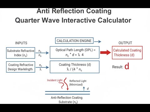
Use the formula below to calculate coating physical thickness.
d = λ / (4n₁)
Where:
- d = Physical thickness of coating layer (nm or μm)
- λ = Design wavelength in vacuum (nm)
- n₁ = Refractive index of coating material (dimensionless)
Optimal Coating Index
Use the formula below to calculate the ideal coating refractive index.
n₁ = √(n₀ × n₂)
Where:
- n₁ = Refractive index of coating (dimensionless)
- n₀ = Refractive index of incident medium, typically air (1.0)
- n₂ = Refractive index of substrate material (dimensionless)
For a glass substrate (n₂ = 1.52) in air (n₀ = 1.0), the ideal coating index is n₁ = 1.233. Magnesium fluoride (MgF₂, n = 1.38) is commonly used despite the mismatch because it provides near-optimal performance with excellent durability.
Reflectance at Design Wavelength
Use the formula below to calculate reflectance for a non-ideal coating index.
R = [(n₀n₂ - n₁²) / (n₀n₂ + n₁²)]²
For non-ideal coating index:
- R = Intensity reflectance (fraction, multiply by 100 for percentage)
- When n₁ = √(n₀n₂), reflectance R = 0 (perfect anti-reflection)
- Deviation from ideal index increases residual reflectance quadratically
Wavelength-Dependent Reflectance
Use the formula below to calculate reflectance at wavelengths away from the design center.
R(λ) = [r₀₁² + r₁₂² + 2r₀₁r₁₂cos(δ)]
Where:
- r₀₁ = (n₀ - n₁) / (n₀ + n₁) — Fresnel reflection coefficient at first interface
- r₁₂ = (n₁ - n₂) / (n₁ + n₂) — Fresnel reflection coefficient at second interface
- δ = (4πn₁d cosθ₁) / λ — Phase change upon reflection (radians)
- θ₁ = Refraction angle in coating layer (radians)
At the design wavelength λ₀, the phase shift δ = π, making cos(δ) = -1, which causes destructive interference between reflections from the two interfaces.
Optical Thickness
Use the formula below to calculate optical path difference through the coating.
OPD = n₁ × d
Where:
- OPD = Optical path difference (nm)
- For quarter-wave coating: OPD = λ/4
- Physical thickness decreases with increasing refractive index
Theory & Engineering Applications of Quarter-Wave Anti-Reflection Coatings
Anti-reflection coatings represent a fundamental application of thin-film interference physics, exploiting the wave nature of light to suppress unwanted reflections at optical interfaces. When light transitions between media with different refractive indices—such as from air (n ≈ 1.0) to glass (n ≈ 1.5)—approximately 4-5% of incident light reflects from the surface due to the impedance mismatch. For multi-element optical systems containing dozens of air-glass interfaces, these cumulative losses can reduce transmission by 30-50%, severely degrading image quality and light throughput. The quarter-wave coating addresses this fundamental challenge through precise destructive interference.
Physical Principles and Interference Mechanics
The quarter-wave anti-reflection coating operates on the principle of thin-film interference, creating two reflected waves with precisely controlled phase relationships. When light encounters the coated surface, partial reflection occurs at both the air-coating interface and the coating-substrate interface. The coating thickness is engineered so that the optical path difference between these two reflections equals exactly one-half wavelength. Since reflection from the optically denser medium introduces an additional π phase shift, the two reflected waves arrive 180° out of phase, producing destructive interference that cancels the reflection.
The mathematical condition for this cancellation requires the optical thickness (n₁d) to equal λ/4, where λ represents the design wavelength measured in the coating medium. Critically, the coating refractive index must satisfy n₁ = √(n₀n₂) for complete cancellation—a condition that follows from equating the Fresnel reflection coefficients at both interfaces. For standard optical glass with n₂ = 1.52 in air, the ideal coating index is 1.233. However, no common durable material possesses this exact value, leading to practical compromises in coating design.
Material Selection and Practical Constraints
Magnesium fluoride (MgF₂) dominates commercial quarter-wave coating applications despite its non-ideal refractive index of 1.38 at 550 nm. This material offers exceptional combination of adequate index value, excellent optical transparency across UV-visible-NIR spectrum (200-7000 nm), mechanical durability, low absorption, and compatibility with physical vapor deposition processes. The index mismatch from ideal produces residual reflectance of approximately 1.3% instead of theoretical zero, representing acceptable performance for most applications.
For specialized applications requiring lower reflectance, porous silicon dioxide coatings can achieve indices as low as 1.25 through controlled porosity, approaching the ideal value for glass substrates. However, porous coatings exhibit reduced mechanical durability and environmental stability compared to dense MgF₂ films. High-index substrates like silicon (n = 3.5) or germanium (n = 4.0) require coating materials with indices near 1.87 and 2.0 respectively—values achievable with materials like aluminum oxide (Al₂O₃, n = 1.65) or cerium oxide (CeO₂, n = 2.2), though perfect matching remains challenging.
Wavelength Dependence and Spectral Bandwidth
A critical limitation of single-layer quarter-wave coatings is their inherently narrow spectral bandwidth. The coating provides optimal anti-reflection performance only at the design wavelength where the optical thickness precisely equals λ/4. As the operating wavelength deviates from this design value, the phase relationship between interfering waves shifts from 180°, reducing destructive interference effectiveness. Reflectance increases progressively with wavelength deviation, typically reaching 0.5% at wavelengths ±10% from the design center.
For broadband applications spanning significant spectral ranges—such as photographic objectives covering 400-700 nm or telecommunications components operating across C and L bands—multilayer coatings become necessary. These advanced designs employ three to seven layers with carefully optimized thicknesses and refractive indices, achieving reflectances below 0.25% across bandwidths exceeding 200 nm. However, the manufacturing complexity and cost increase substantially with layer count, making single-layer quarter-wave coatings preferred for narrowband or cost-sensitive applications.
Angular Dependence and Oblique Incidence Effects
Quarter-wave coating performance degrades at oblique incidence angles due to two distinct mechanisms: increased optical path length through the coating and polarization-dependent reflection coefficients. As incidence angle increases, the effective thickness experienced by the light beam increases proportionally to 1/cosθ, shifting the coating's optimal performance to shorter wavelengths. Additionally, s-polarized and p-polarized light exhibit different reflection characteristics at non-normal angles, causing the coating to perform differently for each polarization state.
For optical systems with small numerical apertures (f/8 or slower), angular effects remain negligible with performance degradation less than 0.1% up to 15° incidence. However, fast optical systems (f/2 or faster) encounter light rays spanning ±20° or more, requiring modified coating designs that account for average angle of incidence. Some applications employ gradient-index or inhomogeneous coatings with spatially varying properties to maintain performance across varying local incidence angles.
Worked Example: Designing a Green Laser Anti-Reflection Coating
Consider designing a quarter-wave anti-reflection coating for a frequency-doubled Nd:YAG laser window operating at 532 nm. The substrate is fused silica (n₂ = 1.4607 at 532 nm), and we'll use MgF₂ coating material (n₁ = 1.3777 at 532 nm). The coating will be deposited in vacuum and operate in air (n₀ = 1.0003, approximated as 1.0).
Step 1: Calculate required coating thickness
Using the quarter-wave condition: d = λ / (4n₁)
d = 532 nm / (4 × 1.3777) = 532 / 5.5108 = 96.55 nm
Step 2: Calculate optical thickness
OPD = n₁ × d = 1.3777 × 96.55 nm = 133.0 nm = λ/4 ✓
Step 3: Determine ideal coating index for comparison
n₁(ideal) = √(n₀ × n₂) = √(1.0 × 1.4607) = 1.2086
Actual index deviation: (1.3777 - 1.2086) / 1.2086 × 100% = 14.0% higher than ideal
Step 4: Calculate residual reflectance at design wavelength
R = [(n₀n₂ - n₁²) / (n₀n₂ + n₁²)]²
R = [(1.0 × 1.4607 - 1.3777²) / (1.0 × 1.4607 + 1.3777²)]²
R = [(1.4607 - 1.8981) / (1.4607 + 1.8981)]²
R = [(-0.4374) / (3.3588)]² = (-0.1302)² = 0.01695 = 1.70%
Step 5: Compare to uncoated reflectance
R₀ = [(n₀ - n₂) / (n₀ + n₂)]²
R₀ = [(1.0 - 1.4607) / (1.0 + 1.4607)]² = (-0.4607 / 2.4607)²
R₀ = 0.03507 = 3.51%
Performance assessment: The MgF₂ coating reduces reflectance from 3.51% to 1.70%, representing 51.6% reduction in reflected light. While not achieving zero reflectance due to index mismatch, this performance proves acceptable for most laser applications. The coating requires precise thickness control within ±2 nm to maintain performance specifications, achievable with modern ion-assisted deposition monitoring systems using optical thickness control rather than physical thickness measurement.
Manufacturing Considerations and Deposition Technologies
Physical vapor deposition (PVD) methods dominate quarter-wave coating production, with electron-beam evaporation and ion-beam sputtering as primary techniques. Electron-beam evaporation offers high deposition rates (0.5-5 nm/s) and excellent material utilization, making it economical for high-volume production. However, the process requires precise optical monitoring to achieve target thickness, as physical thickness measurement proves inadequate due to tooling factor variations and density variations in deposited films.
Modern coating systems employ in-situ optical monitoring, measuring transmittance or reflectance at multiple wavelengths during deposition. The coating process continues until measured optical performance reaches predetermined values, automatically compensating for deposition rate variations and material property differences. Ion-assisted deposition (IAD) and plasma ion-assisted deposition (PIAD) techniques bombard the growing film with energetic ions, densifying the coating structure and improving environmental stability at the cost of reduced deposition rate and increased equipment complexity.
For additional technical resources on optical system design and precision engineering, visit the engineering calculator library which includes tools for lens design, optical power calculations, and photometric analysis.
Practical Applications
Scenario: Camera Lens Manufacturing Quality Control
Jennifer, an optical engineer at a premium camera lens manufacturer, needs to verify that a batch of newly coated objective elements meets transmission specifications for a 50mm f/1.4 lens designed for professional photography. The lens contains 8 elements with 14 air-glass interfaces, and each element has a quarter-wave MgF₂ coating optimized for 550 nm (peak photopic sensitivity). She measures a coating thickness of 99.82 nm on a BK7 glass substrate (n = 1.519 at 550 nm) using ellipsometry. Using the anti-reflection calculator, she confirms the coating provides 1.31% reflectance per surface instead of the 4.26% uncoated value—a 69% reduction. Multiplied across all 14 surfaces, the coated lens achieves 82.1% total transmission versus only 54.3% uncoated, meeting the design specification of >80% and justifying the production cost of the coating process.
Scenario: Solar Panel Efficiency Optimization
Marcus, a photovoltaic research scientist, is developing anti-reflection coatings for silicon solar cells to maximize power conversion efficiency. Standard uncoated silicon (n = 3.88 at 600 nm) reflects 35.2% of incident light, representing enormous energy loss. He needs to design a single-layer coating that minimizes reflection in the peak solar spectrum (500-700 nm). Using the calculator's index calculation mode with n₀ = 1.0 (air) and n₂ = 3.88 (silicon), he determines the ideal coating index of 1.97. He selects silicon nitride (Si₃N₄, n = 2.05) as a practical material close to ideal, then calculates the required thickness: 73.17 nm for 600 nm design wavelength. The calculator's bandwidth mode reveals this coating maintains reflectance below 5% across 450-750 nm, covering 87% of the solar spectrum's energy. This single-layer coating increases cell efficiency by 2.8 percentage points absolute—worth $14,000 per MW of installed capacity over a 25-year lifetime, easily justifying the $0.12/watt coating cost.
Scenario: Laser Safety Window Design
Dr. Kenji Yamamoto, a laser safety engineer at a semiconductor fabrication facility, must design protective observation windows for a clean room containing 193 nm ArF excimer lasers used in photolithography. The windows must provide high transmission at visible wavelengths for operator observation while protecting against scattered UV laser radiation. He uses fused silica substrates (n = 1.5076 at 550 nm) and needs to calculate MgF₂ coating thickness (n = 1.38) optimized for 550 nm to maximize visible transmission for comfortable viewing. The calculator determines 99.64 nm thickness provides minimum reflectance at the photopic peak. For the 193 nm laser wavelength, the same coating thickness creates an optical thickness of 0.712λ rather than 0.25λ, resulting in 8.3% reflectance—actually beneficial as it provides additional protection against UV scatter. The coating simultaneously optimizes visible transmission for observation (R = 1.3% at 550 nm, T = 97.4%) while providing inherent UV reflection, eliminating the need for separate UV-blocking filters and simplifying the window design.
Frequently Asked Questions
Why doesn't a quarter-wave coating eliminate all reflection? +
How do I choose the design wavelength for my application? +
What happens to coating performance at angles other than normal incidence? +
Can quarter-wave coatings be used in the ultraviolet or infrared regions? +
How does coating thickness tolerance affect performance? +
Why does my coated optic show colored reflections instead of appearing uniformly dark? +
Free Engineering Calculators
Explore our complete library of free engineering and physics calculators.
Browse All Calculators →🔗 Explore More Free Engineering Calculators
About the Author
Robbie Dickson — Chief Engineer & Founder, FIRGELLI Automations
Robbie Dickson brings over two decades of engineering expertise to FIRGELLI Automations. With a distinguished career at Rolls-Royce, BMW, and Ford, he has deep expertise in mechanical systems, actuator technology, and precision engineering.
Need to implement these calculations?
Explore the precision-engineered motion control solutions used by top engineers.


