If you undercut wall thickness, you risk print failures in 3D printing, injection molding defects, and CNC parts that won't make it out of the machine. All this happens before a single product is in a customer’s hands. The calculator below will give you both minimum and suggested wall thickness, factoring in your process, material, and feature size. This is relevant for any process where wall geometry determines if a part makes it out the door: 3D printing, molding, CNC, sheet metal, and die casting. The rest of the page lays out a formula, examples, practical guidelines, and an FAQ.
What is minimum wall thickness?
Minimum wall thickness is simply the thinnest part of a wall you can get away with and still have a part that comes out of the machine in one piece. If you specify thinner than this, you’ll either see manufacturing failures or parts that break during routine use.
Simple Explanation
Practically, if a mold’s channel is too small, material won’t make it through—plain and simple. Molten plastic, powdered metal, or resin all need a path that doesn’t bottleneck. The minimum wall thickness is not a theoretical limit, but the slimmest you can specify and still have a reliable part off your chosen process and material.
📐 Browse all 1000+ Interactive Calculators
Wall Thickness Design Considerations

Minimum Wall Thickness Calculator
How to Use This Calculator
This calculator is intended for education, concept evaluation, and preliminary design. Results are based on the equations and assumptions described on this page, but cannot account for every real-world load case, tolerance, material property, environmental condition, installation detail, safety factor, code, or regulatory requirement. Verify all inputs, assumptions, units, and results independently before selecting components or using the result in a real application. Safety-critical, structural, medical, lifting, transportation, or regulated applications must be reviewed by a qualified engineer.
- Pick your manufacturing process (FDM, injection molding, CNC, etc.).
- Choose material (ABS, aluminum, PC, etc.).
- Enter the key feature size in millimeters—the actual wall or feature you’re designing.
- Click Calculate for results.
📹 Video Walkthrough — How to Use This Calculator
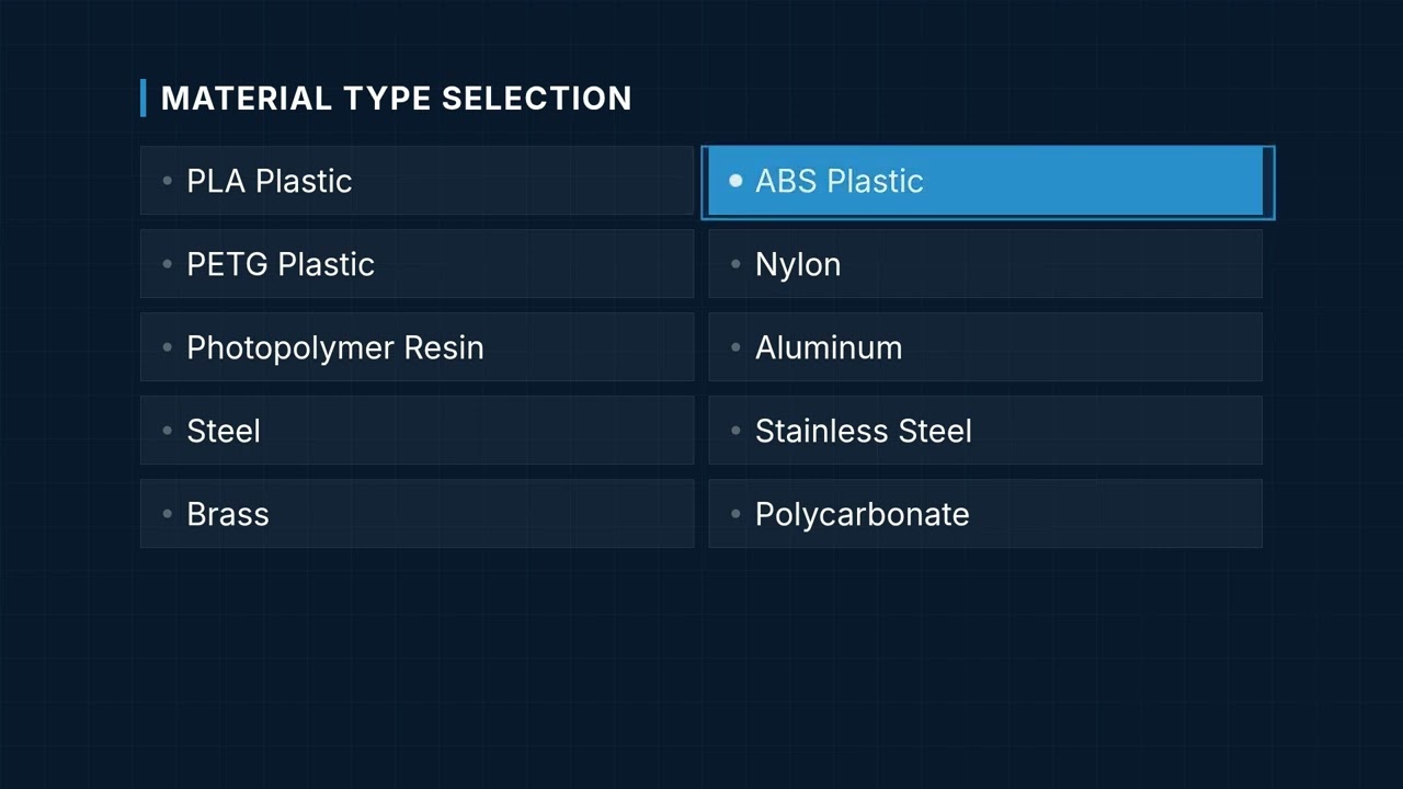
Wall Thickness interactive visualizer
This tool shows how changes to process, material, feature size, and safety factor affect wall thickness. Adjust settings and watch the cross-section update so you can see directly how your wall design would shift in the real world.
MINIMUM THICKNESS
0.88 mm
RECOMMENDED
1.14 mm
FEASIBILITY
GOOD
FIRGELLI Automations — Interactive Engineering Calculators
Equations and Design Guidelines
Minimum wall thickness is a moving target: it depends a lot on process, material, and geometry. The calculation below uses process norms and known limits from shop experience and process specs:
Use the formula below to calculate minimum wall thickness.
Basic Formula:
tmin = tbase × fmaterial × fprocess × fsize
Where:
- tmin = Minimum recommended wall thickness
- tbase = Process baseline thickness
- fmaterial = Material strength factor
- fprocess = Process capability factor
- fsize = Feature size scaling factor
Safety Factor Application:
trecommended = tmin × 1.3
Simple Example
Process: FDM 3D printing. Material: ABS. Feature size: 20 mm.
- tbase = 0.8 mm, fmaterial = 1.1, fprocess = 1.0, fsize = 1.0
- Minimum thickness = 0.8 × 1.1 × 1.0 × 1.0 = 0.88 mm
- Recommended thickness = 0.88 × 1.3 = 1.14 mm
Complete Technical Guide to Manufacturing Wall Thickness
Understanding Wall Thickness Requirements
Wall thickness directly impacts part strength, how easy something is to make, and how much it costs. Get it wrong and you’re likely to have failed prints, scrapped moldings, wasted time, or material you can’t afford. The minimum wall thickness calculator gives a starting point that balances structure with cost and process limits.
Each process has specific limitations. These come from machine hardware, material flow, and how tools or molds actually grip, push, or cut your geometry. If you ignore these factors, you won’t get reliable parts.
Manufacturing Process Considerations
3D Printing Processes
For FDM printers, expect walls in the 0.8-1.2mm range—the real limit comes from nozzle size and how well layers hold together. You generally need at least two perimeters to get anything reliably strong.
SLA (resin) printers can do finer detail, sometimes down to 0.4mm, but at that thickness parts are fragile and can be hard to clean up. Don’t expect to use every bit of that resolution for load-bearing features.
SLS (powder bed) handles around 0.6-0.8mm with much better strength, since the sintered powder itself supports thin sections as they build.
Traditional Manufacturing Methods
With injection molding, you need to consider both fill and cooling. Typical minimums are 0.5-2.0mm depending on plastic and feature size. Uniform wall thickness is key here—if you don’t keep thickness even, you risk warping, sink, or filling issues.
CNC machining is limited by tool diameter, material, and wall height. Thin walls flex under cutting loads, and tools deflect. In practice, you’ll rarely want to go below 1.0-3.0mm, especially as the depth increases or in softer metals.
Sheet metal wall thickness is limited to the material stock, but bends and features still require you to consider minimum bend radii and rules to avoid tearing or warping.
Material Property Impact
The stronger the material, the thinner you can go—but there’s always a process lower bound. Steel and aluminum let you go thinner than most plastics, but again, if you can’t machine or mold it, the material’s strength doesn’t help much.
Certain plastics flow better and fill thin sections more consistently. If you’re molding, pick a material with high melt flow for slender walls. In 3D printing, parts with better layer bonding can be made thinner, but don’t forget that brittle plastics chip or crack well before yielding in the math.
Always account for brittleness: a calculated minimum might survive on paper but snap during handling or assembly.
Design Optimization Strategies
Optimizing wall thickness is a balancing act. Thicker walls help with strength but add weight and use more material. Overbuilding is wasteful; underbuilding costs more in the long run if parts fail in production. Use ribs and gussets to reinforce key regions rather than making the entire wall thick.
In molded and printed parts, adding geometry (ribs/gussets) is often a better investment than bulk wall thickness. This also keeps cycle times and material use down.
For parts that see load only in spots, vary wall thickness by region. Just keep transitions gradual—abrupt changes cause trouble in flow and stress.
Practical Application Example
Say you’re designing a 3D printed ABS enclosure: 150mm × 100mm × 50mm with posts and louvers.
On an FDM machine with a 0.4mm nozzle:
- Base minimum thickness: 0.8mm
- ABS material factor: 1.1
- Large feature size factor: 0.95
- Process factor: 1.0
Calculated minimum thickness = 0.8 × 1.1 × 0.95 × 1.0 = 0.84mm
Recommended thickness with safety factor = 0.84 × 1.3 = 1.09mm
In practice, I’d call out 1.2mm in CAD. Set your slicer for 2–3 perimeters. Internal ribs can be 0.8mm if they’re not load-bearing.
Integration with Automation Systems
When building hardware for automation, wall thickness hits critical importance. For example, mounting points for FIRGELLI linear actuators need enough material to stay rigid and keep fasteners from breaking through, but tolerances also matter so actuators sit square and work smoothly.
Brackets and housings that see dynamic loads usually need beefed-up walls or bosses at loading points. This calculator helps dial in those dimensions before you cut the first piece or order a mold.
Quality Control and Testing
The thinner your wall, the more critical your process control. Small measurement errors mean much more in thin sections. Set up inspection routines tuned for your minimums, and be ready for more scrap if you’re running close to the edge.
Don’t just check size—make sure sample parts perform at wall thickness. For cases under load or pressure, destructive or real-use testing is often the best teacher for thin-walled designs.
Watch process parameters like temperature, fill speed, and tool condition. Margins get thin—literally—as you push wall thickness lower.
Cost-Benefit Analysis
Slimming walls cuts material and often cycle time, but costs rise fast if your scrap or troubleshooting goes up. Best value is usually found 20–40% above the calculated minimum, which keeps your rejection rate down but still delivers a lighter, cheaper part.
Advanced Considerations
When it matters most, use FEA to stress test your thickness assumptions. This is especially true for custom-built or load-bearing parts. You might find areas where you can thin out more, or discover spots that need a little extra meat for safety.
For optimized material use, topology optimization can point out non-intuitive places to add or subtract thickness—but expect to do several design-test cycles in the real world to prove these results.
Some simulation tools can predict fill, warping, or tool deflection. Use them early, before you send parts for prototyping or tooling.
Frequently Asked Questions
📐 Browse all 1000+ Interactive Calculators →
About the Author
Robbie Dickson
Chief Engineer & Founder, FIRGELLI Automations
Robbie Dickson brings over two decades of engineering expertise to FIRGELLI Automations. With a distinguished career at Rolls-Royce, BMW, and Ford, he has deep expertise in mechanical systems, actuator technology, and precision engineering.
Need to implement these calculations?
Explore the precision-engineered motion control solutions used by top engineers.


