Designing optical systems, solar arrays, radar hardware, or acoustic spaces all comes down to one deceptively simple parameter: the angle at which a wave hits a surface. Get it wrong and you lose energy to reflection, miss a critical angle threshold, or send a refracted beam in the wrong direction. Use this Angle of Incidence Calculator to calculate the angle of incidence, refraction angle, critical angle, Brewster's angle, or refractive index using geometry or Snell's Law inputs. It matters across photovoltaics, fiber optics, RF antenna design, and architectural acoustics. This page includes the core formulas, a worked solar panel example, full theory, and an FAQ.
What is angle of incidence?
The angle of incidence is the angle between an incoming wave — light, sound, or other electromagnetic radiation — and the imaginary line perpendicular to the surface at the point where the wave hits. That perpendicular line is called the normal. Everything from how much light reflects off glass to how a fiber optic cable traps light depends on this angle.
Simple Explanation
Think of shining a flashlight at a mirror. If you hold it straight in front of the mirror, the light bounces straight back — that's 0° incidence. Tilt the flashlight to the side and the reflected beam swings away at the same angle you tilted. The angle of incidence is just how far off "straight-on" your incoming beam is. The steeper the angle, the more the wave bends, reflects, or gets blocked when it hits the surface.
📐 Browse all 1000+ Interactive Calculators
How to Use This Calculator
- Select a calculation mode from the dropdown — choose from angle from position, refraction angle, critical angle, Brewster's angle, or refractive index.
- Enter the required inputs for your selected mode — horizontal distance and vertical height, or incident angle and refractive indices, depending on the mode.
- Check your values are positive and within valid ranges (angles between 0° and 90°, refractive indices greater than 0).
- Click Calculate to see your result.
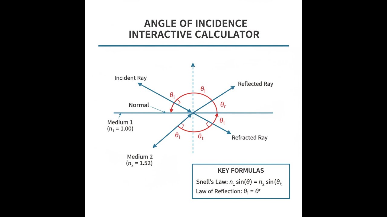
Angle of Incidence Diagram

Interactive Angle of Incidence Calculator
Angle of Incidence Interactive Visualizer
Watch how incident rays interact with surfaces through reflection and refraction. Adjust the incident angle to see real-time changes in reflected and refracted beam paths, with automatic calculations for critical angles and Brewster's angle.
REFRACTION ANGLE
19.5°
CRITICAL ANGLE
41.8°
BREWSTER ANGLE
56.3°
REFLECTION
PARTIAL
FIRGELLI Automations — Interactive Engineering Calculators
Equations & Variables
Use the formula below to calculate angle of incidence, refraction angle, critical angle, and Brewster's angle.
Angle from Geometry:
θi = arctan(h / d)
Snell's Law (Refraction):
n1 sin(θi) = n2 sin(θt)
Critical Angle:
θc = arcsin(n2 / n1)
(valid only when n1 > n2)
Brewster's Angle:
θB = arctan(n2 / n1)
Variable Definitions
- θi = Angle of incidence (degrees or radians) — angle between incident ray and surface normal
- θr = Angle of reflection (degrees or radians) — always equals θi by law of reflection
- θt = Angle of refraction/transmission (degrees or radians) — angle of refracted ray from normal
- θc = Critical angle (degrees or radians) — minimum incident angle for total internal reflection
- θB = Brewster's angle (degrees or radians) — angle at which reflected light is perfectly polarized
- n1 = Refractive index of incident medium (dimensionless) — typically air = 1.00
- n2 = Refractive index of transmitted medium (dimensionless) — glass ≈ 1.5, water ≈ 1.33
- h = Vertical height or perpendicular distance (meters)
- d = Horizontal distance from normal (meters)
Simple Example
A light ray travels from air (n₁ = 1.0) into glass (n₂ = 1.5) at an incident angle of 45°. Using Snell's Law: 1.0 × sin(45°) = 1.5 × sin(θₜ), so sin(θₜ) = 0.4714, giving a refraction angle of 28.1°. The ray bends toward the normal as it enters the denser medium — 16.9° of bending total.
Theory & Practical Applications
Fundamental Physics of Incidence Angles
The angle of incidence fundamentally determines wave behavior at material interfaces through 3 primary mechanisms: reflection, refraction, and absorption. When electromagnetic radiation or acoustic waves encounter a boundary between media with different propagation velocities, the wavefront must satisfy boundary conditions that preserve phase continuity across the interface. This constraint, combined with energy and momentum conservation, produces Snell's law and the law of reflection. The incident angle's influence extends beyond simple geometric optics — it governs polarization-dependent reflectance (Fresnel equations), determines coupling efficiency in fiber optics, affects antenna radiation patterns, and controls solar irradiance on photovoltaic surfaces.
A critical but often overlooked aspect is the distinction between local and global angles of incidence. In optical systems with curved surfaces, the relevant angle is measured relative to the local surface normal at each point, not the overall geometry. For rough surfaces at microscopic scales, individual facets each have unique local normals, causing diffuse scattering even when the macroscopic surface appears smooth. This becomes critical in solar panel design: a 10° manufacturing tolerance in panel tilt translates to roughly 15% variation in cosine loss at 60° solar zenith angles, but less than 2% variation at 30° zenith angles. Engineers must account for this nonlinear sensitivity when specifying installation tolerances.
Snell's Law and Refractive Index Variations
Snell's law, n₁ sin(θᵢ) = n₂ sin(θₜ), governs refraction at planar interfaces but requires modification for real-world conditions. Refractive indices are wavelength-dependent (dispersion), causing chromatic aberration in optical systems and rainbow formation in atmospheric optics. For precision applications, the Sellmeier equation or Cauchy equation provides wavelength-dependent n(λ) values. In fiber optics operating near 1550 nm, silica glass has n ≈ 1.444, but manufacturing tolerances of ±0.001 in core/cladding index difference dramatically affect numerical aperture and mode propagation. Temperature also influences refractive index: standard optical glass exhibits dn/dT ≈ 1×10⁻⁶ K⁻¹, requiring thermal compensation in high-precision interferometers.
The critical angle phenomenon, θc = arcsin(n₂/n₁) for n₁ > n₂, enables total internal reflection (TIR) — the foundation of fiber optic communication, prism retroreflectors, and binoculars. However, TIR is not perfect; evanescent waves penetrate approximately one wavelength into the lower-index medium, causing frustrated total internal reflection when a third medium is brought within this distance. This effect is exploited in optical couplers and TIRF microscopy, but represents a parasitic loss mechanism in multimode fibers where cores are spaced too closely.
Brewster's Angle and Polarization Effects
Brewster's angle, θB = arctan(n₂/n₁), represents the unique incident angle where p-polarized light (electric field parallel to the plane of incidence) experiences zero reflection — all energy transmits into the second medium. At this angle, reflected and refracted rays are perpendicular (θB + θt = 90°), causing the reflected electric field to align with its own propagation direction — physically impossible, thus zero reflection. S-polarized light (perpendicular to plane of incidence) still reflects at Brewster's angle, producing highly polarized reflected beams.
This effect has immediate practical applications. Polarizing filters at laser Brewster windows eliminate reflection losses without absorptive coatings, achieving >99.5% transmission for p-polarized light. Photographers use polarizing filters most effectively at θB ≈ 53° from horizontal water surfaces (n ≈ 1.33) to eliminate glare. In architectural glass, reflection control coatings are designed knowing that vertical window surfaces primarily encounter light near Brewster's angle (56° for standard glass) from low-sun conditions, while overhead light hits near normal incidence.
Solar Energy Applications and Cosine Losses
Photovoltaic efficiency depends critically on angle of incidence through 2 mechanisms: cosine projection loss and angle-dependent reflectance. The cosine loss factor, cos(θᵢ), reduces effective irradiance from the nominal 1000 W/m² at normal incidence to 866 W/m² at 30° and only 500 W/m² at 60°. For fixed-tilt arrays, the optimal tilt angle equals site latitude to maximize annual energy capture, but this represents a compromise — summer performance would improve with lower tilt, winter with higher tilt.
Reflectance at the glass-air interface adds another angle-dependent loss. Standard solar glass has n ≈ 1.52; at normal incidence, Fresnel reflection losses are approximately 4%. However, at 60° incidence, reflection increases to 12%, and at 80°, exceeds 40%. Antireflective coatings reduce normal-incidence losses to <2%, but their effectiveness decreases at oblique angles. This creates a "morning/evening cliff" where panel output drops sharply beyond 60° incidence angles. Dual-axis trackers maintain near-normal incidence throughout the day, increasing energy capture by 25-35% compared to fixed arrays, but add mechanical complexity and maintenance requirements.
Optical Fiber and Total Internal Reflection
Single-mode and multimode optical fibers exploit total internal reflection to guide light over kilometers with minimal loss. The fiber's numerical aperture (NA) defines the maximum acceptance angle: NA = √(n₁² - n₂²), where n₁ is core index and n₂ is cladding index. For typical single-mode fiber with n₁ = 1.4681 and n₂ = 1.4628 at 1550 nm, NA ≈ 0.12, corresponding to a half-angle acceptance cone of approximately 6.9°. Light entering beyond this angle will not undergo TIR and escapes into the cladding.
In multimode fibers with larger NA (typically 0.2-0.3), many propagation modes exist simultaneously, each corresponding to a different zigzag path down the fiber. Modal dispersion causes pulse spreading because different modes travel different path lengths. A ray entering at the maximum acceptance angle travels approximately 1/NA times farther than an axial ray, limiting bandwidth-distance products to approximately 500 MHz·km for standard 50 μm graded-index multimode fiber, compared to effectively unlimited bandwidth for single-mode fiber.
Worked Example: Solar Panel Array Optimization
Problem: A commercial solar installation in Denver, Colorado (latitude 39.74°N) uses fixed-tilt panels with n = 1.52 glass. Calculate the optimal tilt angle, critical angle for total internal reflection from the back surface, and the effective reduction in irradiance at 7:00 AM on June 21 when the solar elevation angle is 23.6° and azimuth is 67° east of south. The panel azimuth is due south.
Part A: Optimal Tilt Angle
For maximum annual energy capture at latitude φ = 39.74°, optimal fixed-tilt angle approximately equals latitude: α = 40° (rounded for practical mounting).
Part B: Critical Angle for Back Surface TIR
Assuming glass (n₁ = 1.52) to air (n₂ = 1.00) interface at the back encapsulant:
θc = arcsin(n₂/n₁) = arcsin(1.00/1.52) = arcsin(0.6579) = 41.14°
Any light reaching the back surface at angles greater than 41.14° from normal will undergo total internal reflection, potentially causing internal heating rather than escaping.
Part C: Angle of Incidence Calculation
Solar position: elevation β = 23.6°, azimuth γ = 67° (measured from south toward east). Panel: tilt α = 40°, azimuth 0° (due south).
The angle of incidence θᵢ for a tilted surface is:
cos(θᵢ) = sin(β)cos(α) + cos(β)sin(α)cos(γ)
cos(θᵢ) = sin(23.6°)cos(40°) + cos(23.6°)sin(40°)cos(67°)
cos(θᵢ) = (0.4003)(0.7660) + (0.9165)(0.6428)(0.3907)
cos(θᵢ) = 0.3066 + 0.2301 = 0.5367
θᵢ = arccos(0.5367) = 57.53°
Part D: Cosine Loss and Reflectance Loss
Cosine projection factor: cos(57.53°) = 0.5367, reducing incident irradiance from 1000 W/m² to 536.7 W/m².
For unpolarized light at θᵢ = 57.53° on glass-air interface (n = 1.52), Fresnel equations give approximately 11.3% reflection loss (requires full Fresnel calculation for precision). Transmitted power: 0.887 × 536.7 = 476.0 W/m² reaching the cells.
Part E: Comparison to Normal Incidence
At normal incidence (θᵢ = 0°), transmitted power would be approximately 960 W/m² (4% Fresnel loss). The early morning oblique angle reduces power to 476.0 W/m², representing a 50.4% reduction compared to optimal conditions. This demonstrates why tracking systems significantly outperform fixed arrays during morning/evening hours.
Antenna and RF Applications
In RF engineering, angle of incidence affects antenna pattern coupling, ground plane reflections, and radome transmission losses. Patch antennas and phased arrays exhibit gain patterns dependent on θ relative to the normal axis. A typical microstrip patch antenna maintains gain within 3 dB up to approximately ±40° from broadside, but gain drops rapidly beyond this. For satellite communications, maintaining antenna pointing within ±2° is critical to prevent exceeding link budgets.
Ground reflections create multipath interference patterns determined by incidence angles. For a transmitter at height h₁ and receiver at height h₂ separated by distance d, the grazing angle θ ≈ (h₁ + h₂)/d for small angles. Destructive interference occurs when the path length difference equals odd multiples of λ/2, creating null zones in coverage. Cellular tower height and downtilt angle selection must account for these angle-dependent interference effects.
Architectural Acoustics and Sound Reflection
Acoustic waves follow reflection/refraction laws analogous to light, with "refractive index" determined by impedance ratios. In concert hall design, wall panel angles are critical to controlling early reflections — reflections arriving within 50 ms of direct sound enhance clarity, while later reflections cause echo. Specular reflections from flat surfaces follow θᵢ = θᵣ, while diffusing surfaces scatter sound over wide angles through surface roughness comparable to wavelengths (5-10 cm for speech frequencies).
The critical angle concept applies at air-water boundaries in underwater acoustics: sound traveling from water (c ≈ 1500 m/s) to air (c ≈ 343 m/s) has critical angle θc = arcsin(343/1500) = 13.2°. Beyond this angle, total internal reflection traps sound underwater, limiting airborne detection of submerged sources.
Frequently Asked Questions
Free Engineering Calculators
Explore our complete library of free engineering and physics calculators.
Browse All Calculators →🔗 Explore More Free Engineering Calculators
About the Author
Robbie Dickson — Chief Engineer & Founder, FIRGELLI Automations
Robbie Dickson brings over two decades of engineering expertise to FIRGELLI Automations. With a distinguished career at Rolls-Royce, BMW, and Ford, he has deep expertise in mechanical systems, actuator technology, and precision engineering.
Need to implement these calculations?
Explore the precision-engineered motion control solutions used by top engineers.


