Controlling a linear actuator with an Arduino requires an intermediate driver — either a relay pair or an H-bridge motor driver — because Arduino pins output 5V at roughly 40mA while actuators need 12V or 24V at 1–10A. The Arduino sends low-current logic signals; the driver switches the actual motor power.
Arduino microcontrollers have revolutionized the way hobbyists, engineers, and automation enthusiasts approach motion control projects. When combined with linear actuators, they unlock sophisticated positioning, automation, and feedback capabilities that would otherwise require complex industrial PLCs or specialized controllers. Whether you're building a custom standing desk, an automated hatch, a solar tracker, or a TV lift mechanism, understanding how to properly interface an Arduino with an electric linear actuator is essential for success.
This comprehensive guide will walk you through everything you need to know about controlling linear actuators with Arduino boards—from understanding the fundamental hardware requirements to implementing advanced position control with feedback sensors. We'll cover both relay-based and motor driver approaches, examine the practical code examples you need to get started, and explore how to integrate various input devices for fully automated systems. By the end, you'll have the knowledge to design and implement Arduino-controlled actuation systems for virtually any application.
Wiring and mounting matter as much as force. A correctly sized actuator on an undersized power supply, a shared but floating ground, or undergauge wire will misbehave in ways that look like a code bug — and aren't.
"The Arduino doesn't drive the actuator — it tells a relay or motor driver when to drive it. Treat the Arduino as a signal source, not a power source, and size the power supply for startup current, not running current." — Robbie Dickson, Founder and Chief Engineer of FIRGELLI Automations
What is an Arduino and how does it work for motion control?
Arduino is an open-source electronics prototyping platform built around flexible, easy-to-use hardware and software. At its core is a microcontroller—essentially a miniaturized computer optimized for embedded systems—combined with standardized input/output pins, voltage regulation, and USB programming interfaces that eliminate the complexity traditionally associated with microcontroller development.
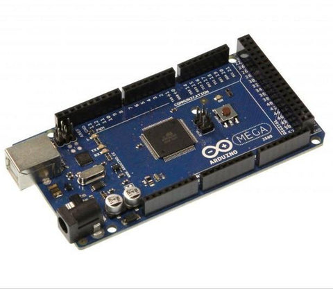
The Arduino family includes several board variations designed for different applications. The Arduino Mega offers the most I/O pins and memory, making it ideal for complex multi-actuator systems. The Arduino Uno strikes the best balance between capability and simplicity, which is why it's become the most popular choice for DIY automation projects. The compact Arduino Pro Mini saves space in permanent installations where size constraints matter.
What makes Arduino particularly valuable for actuator control is its free, open-source IDE (Integrated Development Environment) that uses a simplified version of C++. The programming language is approachable enough for beginners while remaining powerful enough for advanced applications. Thanks to Arduino's massive global community, you'll find extensive libraries, code examples, and troubleshooting resources specifically focused on motor control and automation projects.
For newcomers to microcontroller programming, Arduino starter kits provide everything needed to begin: jumper wires, breadboards, sensors, relays, and the Uno board itself. This makes the learning curve manageable even for those without prior electronics experience.
Why use an Arduino to control a linear actuator?
While simple toggle switches and basic control boxes work well for straightforward applications, Arduino-based control systems unlock capabilities that aren't possible with standard wiring approaches.
Complex Input Processing: Microcontrollers can simultaneously monitor multiple sensors—limit switches, temperature sensors, light sensors, or distance sensors—and make intelligent decisions about actuator positioning based on real-time conditions. For example, a solar panel tracking system might use light sensors and time-of-day calculations to optimize panel angles throughout the day.
Precise Position Control: When paired with feedback actuators that provide position data, Arduinos enable closed-loop control systems that can position actuators to specific points with sub-millimeter accuracy. This is essential for applications like camera sliders, precision testing equipment, or automated measurement systems.
Automated Sequences: Microcontrollers excel at executing timed sequences and coordinating multiple actuators. You can program complex motion profiles—extend for 5 seconds, pause for 2 seconds, retract at half speed—or synchronize several actuators to move in precise coordination.
Speed Modulation: Unlike simple relay switches that only offer full-speed operation, Arduino control with PWM (pulse-width modulation) allows variable speed control. This reduces noise, minimizes mechanical stress on components, and enables smooth, controlled motion critical for applications like automated window openers or furniture mechanisms.
Safety Features: You can implement sophisticated safety logic—automatic retraction when an obstruction is detected, emergency stop routines, or position limits that prevent over-extension. These software-based safety systems complement physical limit switches for robust protection.
What power and voltage does an Arduino-actuator system need?
A critical concept for anyone new to Arduino-actuator integration is understanding why you cannot directly connect a linear actuator to Arduino output pins the way you might connect an LED or small sensor.
Arduino boards operate at 5V logic levels, and each digital output pin can safely source only about 40mA of current. Most electric linear actuators, by contrast, operate at 12V or 24V and draw anywhere from 1A to over 10A under load—two to three orders of magnitude more current than an Arduino pin can handle. Attempting to power an actuator directly from Arduino pins would immediately damage the microcontroller.
This fundamental mismatch means you need an intermediate control component that acts as a bridge: the Arduino's low-voltage, low-current signal controls this intermediate device, which in turn switches the high-voltage, high-current power to your actuator. The two primary options for this intermediate control are relays and motor drivers, each with distinct advantages.
Regardless of which approach you choose, you'll also need an appropriate power supply capable of delivering sufficient voltage and current for your specific actuator. A 12V actuator drawing 6A under load requires a power supply rated for at least 12V and 8-10A (allowing headroom for startup current spikes).
How do you control a linear actuator with relays?
Relays are electromagnetic switches that allow low-power control signals to switch high-power circuits. When you energize a relay's coil (typically requiring only 50-100mA at 5V), it mechanically closes or opens switch contacts that can handle much higher voltages and currents—perfect for controlling actuators.
Relay Basics and Configuration
For linear actuator control, the most common configuration uses two SPDT (Single-Pole, Double-Throw) relays to achieve bidirectional control. This setup allows you to reverse polarity to the actuator, which is how DC motors change direction. One relay controls extension, the other controls retraction, and when both are de-energized, the actuator stops.
When selecting relays for Arduino projects, ensure the coil voltage rating matches Arduino's 5V output. The contact ratings must exceed your actuator's operating voltage and current—for a 12V actuator drawing 6A, use relays rated for at least 12V and 10A contacts to provide safety margin.
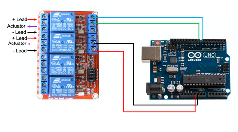
Arduino-to-Relay Wiring
Interfacing Arduino with relays is straightforward but requires attention to detail. Connect the relay coil's positive terminal to an Arduino digital output pin (pins 2-13 on an Uno) and the coil's negative terminal to Arduino ground. When you set that digital pin HIGH (5V), current flows through the coil, energizing the relay and closing its switch contacts.
Many relay modules designed for Arduino include flyback diodes and transistor drivers already integrated on a small PCB, simplifying connections and protecting the Arduino from voltage spikes generated when relay coils de-energize. These modules typically have three-pin connections: VCC (5V), GND (ground), and IN (signal input).
Relay Control Code Example
The following code demonstrates basic actuator control using two SPDT relays connected to Arduino pins 7 and 8. This example creates a simple extend-stop-retract-stop cycle that repeats continuously:
View the relay control code example on GitHub Gist
In this configuration, setting a pin LOW energizes the corresponding relay. Both pins HIGH means both relays are off, disconnecting power and stopping the actuator. The 2-second delays control how long each action persists before transitioning to the next state.
Advantages and Limitations of Relay Control
Relays offer excellent electrical isolation between control and power circuits, are simple to understand and implement, and work reliably for applications requiring basic on/off control. They're ideal for projects where you simply need to extend or retract an actuator fully without intermediate positioning.
However, relay-based control has limitations: you cannot vary actuator speed, relays have finite lifespan due to contact wear (typically 100,000 switching cycles), mechanical switching produces audible clicking, and switching delays of 5-15 milliseconds limit response time. For applications requiring variable speed, precise positioning, or silent operation, motor drivers offer superior performance.
How do you control a linear actuator with a motor driver?
Motor drivers—also called motor controllers or H-bridge modules—are integrated circuits specifically designed to control DC motors with greater sophistication than simple relays allow. They enable both direction control and variable speed through PWM (pulse-width modulation), unlocking smooth, quiet, and precisely controlled actuator movement.
| Attribute | SPDT relay pair | H-bridge motor driver |
|---|---|---|
| Direction control | Yes (polarity reversal) | Yes |
| Variable speed | No | Yes (via PWM) |
| Switching type | Mechanical contacts | Solid-state transistors |
| Switching delay | 5–15 ms | Microseconds |
| Audible noise | Clicking | Silent |
| Lifespan | ~100,000 cycles | Effectively unlimited (electrical) |
| Electrical isolation | Excellent | Limited (shared ground typical) |
| Best for | Simple on/off, full extend/retract | Variable speed, positioning, frequent cycling |
| Driver | Continuous current | Notes |
|---|---|---|
| L293D | ~0.6A per channel | Small actuators only |
| L298N | ~2A per channel | Common hobby choice |
| BTS7960 | Up to 43A | Industrial actuators |
| FIRGELLI High Current DC Motor Drive | High current | LPWM/RPWM control inputs |
Understanding H-Bridge Motor Drivers
At the core of most motor drivers is an H-bridge circuit: an arrangement of four switching transistors that can reverse current direction through a motor while also modulating the effective voltage via PWM. This configuration allows a motor to be driven forward, backward, or stopped, with speed control at any point in between.
Motor drivers handle the high currents required by actuators while accepting low-current logic signals from microcontrollers. They typically include protection features like over-current shutdown, thermal protection, and flyback diode networks that protect against voltage spikes from motor inductance.
Popular motor driver options for Arduino actuator projects include the L298N (dual H-bridge, up to 2A per channel), L293D (good for smaller actuators), BTS7960 (high current, 43A capability for industrial actuators), and FIRGELLI's High Current DC Motor Drive designed specifically for demanding linear actuator applications.
PWM and Speed Control Explained
PWM (pulse-width modulation) rapidly switches power on and off at high frequency (typically 500Hz to 20kHz). By varying the ratio of on-time to off-time—called the duty cycle—you effectively control the average voltage delivered to the motor. A 50% duty cycle delivers approximately half voltage, resulting in half speed. A 25% duty cycle gives quarter speed, and so on.
Arduino represents PWM values as integers from 0 to 255: 0 means completely off (0% duty cycle), 255 means fully on (100% duty cycle), and 127 represents approximately 50% duty cycle. The Arduino Uno has six PWM-capable pins (3, 5, 6, 9, 10, 11), marked with a ~ symbol on the board.
Variable speed control is particularly valuable for micro linear actuators and applications where smooth, quiet operation matters more than raw speed. Reducing actuator speed also decreases mechanical wear and power consumption.
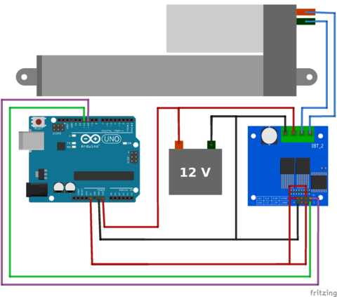
Wiring Arduino to Motor Driver
While specific connection details vary by motor driver model, the general pattern is consistent. You'll need to connect:
- Power inputs: Motor driver power terminals connect to your actuator's power supply (12V, 24V, etc.)
- Ground: Common ground between Arduino, motor driver, and power supply is essential
- Motor outputs: Two terminals connect to your actuator's wire leads
- Control signals: Typically two PWM pins from Arduino connect to direction/speed inputs on the driver
- Logic power: Some drivers need separate 5V logic power from Arduino's 5V pin
For FIRGELLI's High Current DC Motor Drive, the LPWM (Left PWM) and RPWM (Right PWM) inputs control direction and speed: send a PWM signal to LPWM with RPWM at zero to extend, or vice versa to retract. Both at zero stops the actuator.
Motor Driver Control Code Example
This code demonstrates variable speed control using a dual-PWM motor driver connected to Arduino pins 10 and 11:
View the motor driver control code example on GitHub Gist
Notice the use of analogWrite() instead of digitalWrite(). This function accepts values from 0-255 and generates the corresponding PWM signal. The code extends at full speed (255), then retracts at half speed (127), demonstrating the variable speed capability that relay control cannot provide.
Advantages of Motor Driver Control
Motor drivers offer several significant advantages over relay-based systems: silent electronic switching with no mechanical wear, variable speed control for smooth operation, faster response times (microseconds instead of milliseconds), and typically better efficiency. They're the preferred choice for applications requiring precise control, quiet operation, or frequent speed changes—such as camera motion control, automated TV lifts, or synchronized multi-actuator systems.
How do you add position feedback and closed-loop control?
The most powerful Arduino actuator systems incorporate position feedback, transforming open-loop on/off control into precise closed-loop positioning systems. Feedback actuators include built-in sensors—typically potentiometers or Hall effect sensors—that output a voltage proportional to the actuator's extension position.
Reading Feedback Signals
Feedback actuators typically provide three wires in addition to the two motor power wires: power (usually 5V), ground, and signal. The signal wire outputs an analog voltage that varies from near 0V at fully retracted to near 5V at fully extended (for potentiometer-based feedback).
Arduino's analog input pins can read these voltages using the analogRead() function, which returns a value from 0 (0V) to 1023 (5V). By reading this value periodically, your code knows the actuator's current position and can stop it precisely at any desired point.
Basic Position Control Algorithm
A simple position control algorithm continuously compares the desired position (target) with the actual position (from feedback), and moves the actuator in the appropriate direction until the positions match:
- If actual position is less than target position, extend the actuator
- If actual position is greater than target position, retract the actuator
- If actual position equals target position (within tolerance), stop the actuator
More sophisticated implementations add PID (Proportional-Integral-Derivative) control algorithms that adjust speed based on how far from target the actuator is, producing smoother motion and faster settling with less overshoot. These algorithms are well-documented in Arduino libraries and online resources.
Applications for Feedback Control
Position feedback enables applications impossible with basic control: automated solar trackers that adjust to precise angles throughout the day, standing desks with programmable height presets, camera sliders with keyframe positioning, automated vents that modulate opening percentage based on temperature, and multi-actuator systems where synchronized positioning is critical.
How do you add sensors and input devices to an Arduino actuator system?
Once you've established basic actuator control, integrating input devices transforms your system from manually programmed to intelligently responsive. Arduino's extensive I/O capabilities make it straightforward to incorporate various sensors and switches.
Digital Inputs: Switches and Binary Sensors
Digital inputs provide binary (on/off) signals and connect to Arduino's digital pins. Common examples include pushbutton switches for manual control, limit switches for physical position detection, magnetic reed switches for door/window sensing, and PIR motion sensors for automated activation.
Reading digital inputs requires configuring the pin as an input in your setup code with pinMode(pin, INPUT_PULLUP) and checking its state using digitalRead(pin), which returns HIGH or LOW. The INPUT_PULLUP mode activates Arduino's internal pull-up resistor, simplifying wiring by eliminating the need for external resistors.
Analog Inputs: Variable Sensors
Analog inputs read continuously variable voltages from 0-5V and connect to Arduino's analog pins (A0-A5 on the Uno). These enable sophisticated sensing: potentiometers for manual position adjustment, temperature sensors for climate-responsive automation, light sensors (photoresistors) for day/night operation, distance sensors for obstacle detection, and force sensors for load monitoring.
The analogRead() function returns values from 0-1023, which you can scale and interpret based on your sensor's specifications. For example, a temperature sensor outputting 0-5V across a 0-100°C range would require multiplying the analogRead value by (5.0/1023.0) to get voltage, then by (100.0/5.0) to get temperature.
Serial Communication and Wireless Control
Arduino's serial communication capabilities enable integration with computers, smartphones, and wireless modules. You can send commands via USB serial connection, add Bluetooth modules for wireless smartphone control, integrate WiFi modules for IoT connectivity, or use RF modules for remote control at distances up to several hundred meters.
Libraries like SoftwareSerial, WiFi, and various Bluetooth libraries handle the communication protocols, letting you focus on application logic rather than low-level data transmission details.
Multi-Actuator Coordination
Arduino's multitasking capabilities (via timer interrupts or libraries like Arduino-Scheduler) allow simultaneous control of multiple actuators. This is valuable for synchronized systems like multi-point desk lifts, coordinated window operators, or robotic platforms requiring precise movement patterns across several axes.
When controlling multiple actuators, ensure your power supply can handle the combined current draw, and consider whether each actuator needs its own motor driver or if you can multiplex control signals (though independent drivers provide better performance).
What are the best practices for building a reliable Arduino-actuator system?
Successful Arduino-actuator projects require attention to details beyond basic wiring and code. Here are critical considerations drawn from practical implementation experience.
Electrical Safety and Grounding
Always establish a common ground between your Arduino, motor driver, actuator power supply, and any sensors. Ground loops and floating grounds cause erratic behavior and can damage components. Use appropriately rated wire for high-current connections—at least 18 AWG for actuators drawing 5A, heavier gauge for higher currents.
Include a physical emergency stop switch that mechanically disconnects power to actuators, independent of Arduino control. This provides fail-safe protection during testing and troubleshooting.
Mechanical Installation Considerations
Proper mechanical installation is as important as electrical design. Use appropriate mounting brackets to ensure actuators are properly aligned with the load. Misalignment causes binding, accelerates wear, and can lead to premature failure. For applications requiring smooth linear motion over longer distances, consider slide rails or linear guides to support the load and reduce side loading on the actuator.
Always incorporate mechanical stops or limit switches to prevent over-extension, even if you have software limits. Hardware protection provides redundancy against code errors or unexpected conditions.
Code Organization and Debugging
Structure your Arduino code with separate functions for different tasks: one function to read sensors, another to process inputs and make decisions, another to control actuators. This modular approach makes debugging easier and code more maintainable.
Use Arduino's Serial.print() functions extensively during development to output sensor readings, position values, and state information to the Serial Monitor. This real-time visibility into your program's operation is invaluable for troubleshooting.
Implement sensible timeout and safety checks in your code: if an actuator is commanded to extend but feedback shows no movement after 2 seconds, something is wrong—stop the system and signal an error rather than continuing indefinitely.
Power Supply Considerations
Undersized power supplies are a common source of problems. Actuators draw significantly more current during startup and under load than when running free. Select power supplies with at least 30-50% headroom beyond your actuator's rated current draw. For a 12V actuator rated at 6A, use a 12V 9A power supply.
For battery-powered applications, lead-acid or lithium batteries sized appropriately for your duty cycle work well. Remember that battery voltage drops as they discharge, potentially affecting actuator speed and force toward the end of the discharge cycle.
Testing and Validation
Test your system incrementally: verify basic motor driver function before integrating Arduino control, test position feedback accuracy across the full stroke, validate sensor inputs individually before combining them into complex logic. This incremental approach isolates problems to specific subsystems rather than facing debugging a fully integrated system where failures could originate anywhere.
For mission-critical applications, implement error handling and recovery routines. What should happen if feedback is lost? If an actuator stalls? If power is interrupted mid-cycle? Thinking through failure modes and coding appropriate responses distinguishes reliable systems from fragile prototypes.
A practical bring-up checklist:
- Bench-test the driver alone first: jumper the driver inputs directly to 5V/GND and confirm the actuator extends and retracts. This eliminates Arduino code from the variable list.
- Verify common ground with a multimeter between Arduino GND, driver GND, and supply negative — it should read 0V.
- Test under real load, not just free-air. Current draw, speed, and end-of-stroke behavior all change once the actuator is loaded.
- Run full-stroke cycles, not just middle-of-travel jogs. End-stops and feedback edges are where problems hide.
- For feedback systems, sweep the analogRead value across the full stroke and confirm it changes monotonically with no dead zones.
- Run a stall-detection test: physically block the actuator and confirm your timeout or stall current logic shuts power within a couple of seconds.
- Cycle the system repeatedly under real load. A prototype that works once proves the idea; repeated cycles prove the design.
What advanced control techniques can you use with Arduino and actuators?
Once you've mastered basic Arduino-actuator integration, several advanced techniques can enhance performance and capability.
PID Control for Smooth Positioning
PID (Proportional-Integral-Derivative) control algorithms provide much smoother and more precise positioning than simple on/off control. The Arduino PID library simplifies implementation, automatically adjusting actuator speed based on position error to minimize overshoot and settling time. This is particularly valuable for feedback actuator applications requiring rapid, accurate positioning.
Acceleration and Deceleration Profiles
Ramping speed gradually at the start and end of movement reduces mechanical shock, extends component lifespan, and eliminates the jerky motion characteristic of instant on/off control. Implement this by incrementally increasing or decreasing PWM values over time rather than jumping immediately to target speed.
State Machine Programming
For complex automation sequences involving multiple actuators and conditions, state machine programming provides a robust framework. Define discrete states (IDLE, EXTENDING, EXTENDED, RETRACTING, ERROR, etc.) and explicit transitions between them based on sensor inputs and timers. This approach makes code logic clear and prevents impossible state combinations.
Non-Volatile Memory for Settings
Arduino's built-in EEPROM allows storing configuration values that persist through power cycles. Save user-defined position presets, calibration values, or operational parameters that can be recalled after reboot without requiring reprogramming.
What usually goes wrong with Arduino-actuator systems?
Most Arduino-actuator failures cluster around a small set of root causes. Watch for these specifically:
- Powering the actuator directly from Arduino pins — instantly destroys the microcontroller. The mismatch is roughly two orders of magnitude (5V/40mA vs. 12–24V/1–10A).
- Undersized power supply — the system works under no load, then sags or browns out under actual load and during startup current spikes. Size for startup current, not running current.
- Floating or split ground between Arduino, driver, and actuator supply — produces erratic behavior, missed signals, and hard-to-debug glitches that look like code bugs.
- Undersized motor leads — 18 AWG is a floor for ~5A. Thinner wire heats up and drops voltage before the actuator does, robbing force.
- Relay contact wear — mechanical relays are finite (~100,000 cycles). High-cycle applications should use a motor driver instead.
- Mechanical misalignment between actuator and load — binds the rod, increases current draw, and side-loads the actuator. The actuator should never act as the load guide.
- Lost feedback signal — closed-loop code with no feedback will drive the actuator straight into its hard stop. Always add a timeout and a stall current check.
Conclusion
Integrating Arduino microcontrollers with electric linear actuators opens up a world of automation possibilities that would be difficult or impossible with conventional wiring approaches. Whether you choose relay-based control for simple on/off applications or motor driver systems for sophisticated variable-speed positioning, Arduino's accessible programming environment and extensive community support make implementation straightforward even for those new to microcontrollers.
The key to success lies in understanding the fundamental principles: proper electrical interfacing with appropriate current ratings, correct implementation of control algorithms whether simple or complex, thoughtful sensor integration for intelligent response to real-world conditions, and attention to mechanical installation details that ensure reliable long-term operation.
As you develop your Arduino actuator skills, you'll discover that the combination of affordable hardware, open-source software, and a supportive online community makes it possible to create custom automation solutions tailored precisely to your needs—whether that's a home automation project, a research apparatus, an industrial prototype, or an artistic installation. The techniques covered in this guide provide the foundation; your imagination and specific application requirements will guide where you take them next.
Frequently Asked Questions
Can I control a linear actuator directly from Arduino pins?
No, you cannot connect a linear actuator directly to Arduino output pins. Arduino pins operate at 5V and can source only about 40mA of current, while most linear actuators require 12V or 24V and draw 1-10A or more. Connecting an actuator directly would immediately damage your Arduino board. You must use an intermediate control device—either relays or a motor driver—that can handle the actuator's voltage and current requirements while being controlled by Arduino's low-current signals.
Should I use relays or a motor driver to control my linear actuator with Arduino?
The choice depends on your application requirements. Use relays if you only need simple on/off control (full extension/retraction), want electrical isolation between control and power circuits, or are working with very high currents that exceed typical motor driver ratings. Choose a motor driver if you need variable speed control, want silent operation without mechanical clicking, require faster response times, or plan to implement sophisticated positioning algorithms. Motor drivers are generally better for most modern automation projects due to their flexibility and smooth operation.
How many linear actuators can one Arduino control simultaneously?
An Arduino Uno can control multiple actuators limited primarily by available I/O pins and processing capacity rather than absolute number. Each actuator requires 2 digital pins for relay control or 2 PWM pins for motor driver control. The Uno has 14 digital pins (6 with PWM capability), so theoretically you could control 3 actuators with motor drivers (using 6 PWM pins) or up to 7 actuators with relays (using all 14 digital pins). For larger systems, consider an Arduino Mega with 54 digital I/O pins, or use multiplexing techniques. Ensure your power supply can handle the combined current draw of all actuators operating simultaneously.
What is position feedback and do I need it for my Arduino actuator project?
Position feedback means the actuator includes a built-in sensor (typically a potentiometer or Hall effect sensor) that outputs a signal indicating its current extension position. Feedback actuators allow Arduino to know exactly where the actuator is positioned at any moment, enabling precise positioning at specific points rather than just full extension/retraction. You need feedback if your application requires: stopping at intermediate positions, synchronizing multiple actuators precisely, implementing closed-loop position control, or knowing actuator position without physical limit switches. Simple applications that only need full extend/retract cycles don't require feedback.
What are PWM pins and why do I need them for motor driver control?
PWM (Pulse-Width Modulation) pins are special Arduino outputs that can rapidly switch on and off to create variable average voltages. Standard digital pins only output HIGH (5V) or LOW (0V), but PWM pins can output effective voltages anywhere between by varying the percentage of time spent HIGH versus LOW. This is essential for motor driver control because it allows you to vary actuator speed—a 50% PWM signal results in approximately half speed, 25% gives quarter speed, etc. On an Arduino Uno, PWM pins are marked with a ~ symbol and include pins 3, 5, 6, 9, 10, and 11. Motor driver control requires connecting to these PWM-capable pins and using the analogWrite() function rather than digitalWrite().
What power supply specifications do I need for an Arduino-controlled linear actuator system?
Your power supply must match your actuator's voltage rating (typically 12V or 24V) and provide sufficient current for the actuator's maximum draw plus safety margin. Check your actuator's datasheet for rated current—most draw between 1A and 10A depending on size and force capacity. Select a power supply rated for at least 30-50% more current than your actuator's maximum draw to handle startup current spikes and prevent voltage sag under load. For example, a 12V actuator rated at 6A should use a 12V 9A power supply. For multiple actuators, sum their current requirements. The Arduino itself can typically be powered separately via USB during development, or from a 7-12V input when deployed, drawing minimal current compared to the actuator.
My Arduino code runs but the actuator doesn't move. What should I check?
Systematically verify each part of your system. First, confirm power: measure voltage at the driver's power input under load — a sagging supply behaves like no power at all. Second, confirm ground: Arduino GND, driver GND, and supply negative must all be at the same potential — verify with a multimeter. Third, bypass the Arduino: jumper the driver's direction inputs directly to 5V and GND and see if the actuator moves; if it doesn't, the problem is in the driver or wiring, not the code. Fourth, check the control signal: use Serial.print() to confirm the Arduino is actually setting the output pins as expected, and use an LED or scope to confirm the signal reaches the driver. Fifth, check for stall: a binding or misaligned actuator may be drawing maximum current without moving — listen for a hum and feel the actuator (and driver) for heat.
About the author: Robbie Dickson is the Founder and Chief Engineer of FIRGELLI Automations and a former engineer at Rolls-Royce, BMW, Isuzu, and Ford. Wikipedia.
Industry tags: Industrial Automation, Home Automation, DIY / Maker, Robotics, Solar Tracking, Furniture Automation, AV / Home Theater. Mechanism tags: Linear Actuators, H-Bridge Motor Drivers, SPDT Relays, PWM Control, Closed-Loop Position Feedback, PID Control, Arduino Microcontrollers.


