Designing a radio link, telemetry system, or wireless transmitter requires precise control over how your signal occupies the spectrum — get it wrong and you're either wasting power, violating regulatory masks, or degrading SNR. Use this Modulation Interactive Calculator to calculate modulation depth, bandwidth, sideband frequencies, deviation ratios, and power distribution using amplitude, frequency, or phase as your modulation parameter. Engineers in telecommunications, radio broadcasting, wireless instrumentation, and aerospace telemetry rely on these calculations daily. This page includes the core formulas, a worked FM transmitter design example, plain-English theory, and a full FAQ.
What is modulation?
Modulation is the process of encoding information onto a high-frequency carrier wave by varying its amplitude, frequency, or phase. The result is a signal that can travel efficiently through air or cable and be decoded at the receiver.
Simple Explanation
Think of a carrier wave like a blank radio station — it's broadcasting, but saying nothing. Modulation is how you "write" your message onto it. AM does this by making the wave taller or shorter. FM does it by speeding up or slowing down the wave's cycles. PM shifts the timing of the wave. Each method has different tradeoffs for noise, bandwidth, and power.
📐 Browse all 1000+ Interactive Calculators
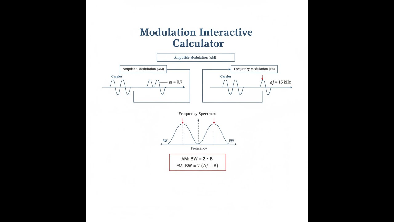
Modulation Diagram

How to Use This Calculator
- Select your modulation type from the dropdown — AM depth, AM power, AM bandwidth, FM deviation, FM index, or PM index.
- Enter the relevant input values for your selected mode (e.g., maximum and minimum amplitude for AM depth, or frequency deviation and modulating frequency for FM index).
- Verify your units match the field labels — frequencies in Hz, amplitudes in volts, power in watts.
- Click Calculate to see your result.
Modulation Interactive Calculator
Modulation Interactive Visualizer
Visualize how amplitude, frequency, and phase modulation encode information onto carrier waves. Watch the spectrum and waveform change in real-time as you adjust modulation parameters.
MODULATION INDEX
3.33
BANDWIDTH
130 Hz
DEVIATION
50 Hz
FIRGELLI Automations — Interactive Engineering Calculators
Modulation Equations
Use the formula below to calculate AM modulation depth, power distribution, and bandwidth.
Amplitude Modulation (AM)
Modulation Depth: m = (Vmax - Vmin) / (Vmax + Vmin)
AM Signal: s(t) = Ac[1 + m·cos(2πfmt)]·cos(2πfct)
Total Power: Pt = Pc(1 + m²/2)
Bandwidth: BW = 2fm
where: m = modulation depth (0 to 1), Vmax/Vmin = max/min envelope voltage (V), Ac = carrier amplitude (V), fc = carrier frequency (Hz), fm = message frequency (Hz), Pc = carrier power (W), Pt = total transmitted power (W)
Use the formula below to calculate FM frequency deviation, modulation index, and bandwidth.
Frequency Modulation (FM)
Frequency Deviation: Δf = kf·Am
Modulation Index: β = Δf / fm
FM Signal: s(t) = Ac·cos[2πfct + β·sin(2πfmt)]
Bandwidth (Carson's Rule): BW ≈ 2(Δf + fm)
where: Δf = frequency deviation (Hz), kf = frequency sensitivity (Hz/V), Am = message amplitude (V), β = modulation index (dimensionless), fm = modulating frequency (Hz), fc = carrier frequency (Hz)
Use the formula below to calculate PM phase deviation and modulation index.
Phase Modulation (PM)
Phase Deviation: Δφ = kp·Am
PM Signal: s(t) = Ac·cos[2πfct + Δφ·cos(2πfmt)]
Modulation Index: βPM = Δφ (radians)
where: Δφ = peak phase deviation (rad), kp = phase sensitivity (rad/V), Am = message amplitude (V), βPM = phase modulation index (rad)
Simple Example
FM modulation index calculation:
- Frequency deviation (Δf): 75,000 Hz
- Modulating frequency (fm): 15,000 Hz
- Modulation index: β = 75,000 / 15,000 = 5.000
- Bandwidth (Carson's Rule): 2 × (75,000 + 15,000) = 180 kHz
Theory & Practical Applications
Fundamental Principles of Modulation
Modulation is the systematic variation of a carrier wave's properties to embed information for efficient transmission through a medium or channel. The carrier—typically a high-frequency sinusoid—serves as a transport mechanism for low-frequency message signals that cannot propagate efficiently through free space or over long distances. The three fundamental modulation parameters are amplitude (A), frequency (f), and phase (φ), corresponding to AM, FM, and PM respectively.
The need for modulation arises from antenna efficiency constraints: efficient radiation requires antenna dimensions on the order of λ/4 to λ/2, where λ is the wavelength. Audio signals (20 Hz to 20 kHz) have wavelengths of 15 km to 15,000 km, making direct radiation impractical. By modulating these signals onto carriers in the MHz to GHz range (wavelengths of meters to millimeters), practical antenna designs become feasible. Additionally, modulation enables frequency-division multiplexing (FDM), allowing multiple signals to occupy distinct spectral bands without interference.
Amplitude Modulation: Analysis & Limitations
In amplitude modulation, the instantaneous amplitude of the carrier varies linearly with the message signal: s(t) = Ac[1 + m·x(t)]·cos(2πfct), where x(t) is the normalized message and m is the modulation depth. For a single tone x(t) = cos(2πfmt), the frequency domain representation reveals a carrier at fc and two sidebands at fc ± fm. The modulation depth m = (Vmax - Vmin) / (Vmax + Vmin) must remain below unity to avoid envelope distortion; when m exceeds 1.0, overmodulation occurs, causing spectral splatter and harmonic distortion that violates regulatory emission masks.
The critical but often overlooked inefficiency in AM is power distribution: the carrier contains no information yet carries most of the transmitted power. For 100% modulation (m = 1), only 33% of total power resides in the sidebands (the information-bearing components). This is why single-sideband suppressed-carrier (SSB-SC) modulation, which eliminates the carrier and one sideband, achieves 12 dB better power efficiency than conventional AM. Commercial AM broadcasting retains full carrier and both sidebands for compatibility with simple envelope detectors in inexpensive receivers, accepting the power penalty for ubiquity.
Frequency Modulation: Carson's Rule & Deviation Ratio
Frequency modulation encodes information by varying the instantaneous frequency of the carrier around fc: fi(t) = fc + kf·x(t). The frequency deviation Δf = kf·Am represents the maximum frequency excursion from the carrier. The modulation index β = Δf / fm determines whether the modulation is narrowband (β much less than 1) or wideband (β greater than 1). Narrowband FM behaves similarly to AM in bandwidth (approximately 2fm), but wideband FM produces theoretically infinite sidebands spaced at fm intervals, with amplitudes governed by Bessel functions Jn(β).
Carson's rule provides a practical bandwidth estimate: BW ≈ 2(Δf + fm) = 2fm(β + 1), capturing approximately 98% of the transmitted power. For commercial FM broadcasting, with Δf = 75 kHz and maximum fm = 15 kHz, β = 5 and BW ≈ 180 kHz (stations are allocated 200 kHz channels). The deviation ratio D = Δfmax / fm(max) is a regulatory parameter—for FM broadcast it equals 5, while narrowband FM (NBFM) used in two-way radio typically has D less than 0.5 with Δf = 2.5-5 kHz.
A counterintuitive aspect of FM is the threshold effect: below a certain carrier-to-noise ratio (typically 10-13 dB), FM demodulator performance degrades catastrophically. Above threshold, FM exhibits superior noise performance compared to AM because noise primarily affects amplitude, and FM limiters suppress amplitude variations. The SNR improvement for wideband FM is approximately 3β², explaining why wide-deviation FM is used for high-fidelity applications despite consuming more bandwidth.
Phase Modulation & Relationship to FM
Phase modulation varies the carrier phase directly: s(t) = Ac·cos[2πfct + kp·x(t)], where kp is phase sensitivity in rad/V. The instantaneous frequency in PM is fi = fc + (kp/2π)·dx/dt, revealing that PM is equivalent to FM when the message is differentiated. Conversely, FM is equivalent to PM with an integrated message. This duality means FM and PM produce identical modulated waveforms for single-tone modulation but differ for complex signals: in PM, the phase deviation is independent of modulating frequency, while in FM, the frequency deviation is constant but phase deviation varies inversely with frequency.
In practice, PM is often preferred in digital communication systems because it directly maps data symbols to distinct phase states (PSK - phase-shift keying), enabling coherent detection with optimal error performance. Frequency modulation finds application in analog systems and continuous-phase modulation schemes like MSK (minimum shift keying) where smooth phase trajectories minimize spectral sidelobes.
Worked Example: FM Transmitter Design for Industrial Telemetry
An industrial sensor outputs 0-5 V representing 0-100°C temperature. Design an FM telemetry link operating at fc = 433.92 MHz (ISM band) with maximum allowable bandwidth of 150 kHz to avoid interfering with adjacent channels. The sensor bandwidth is DC to 50 Hz (slow-varying temperature).
Step 1: Determine frequency deviation. Using Carson's rule BW = 2(Δf + fm) and setting fm = 50 Hz (maximum message frequency), we get: 150,000 = 2(Δf + 50), solving yields Δf = 74,950 Hz ≈ 75 kHz. This is the maximum frequency swing from carrier.
Step 2: Calculate modulation index. β = Δf / fm = 75,000 / 50 = 1500. This is extremely high, classifying this as wideband FM. The large β provides excellent noise immunity critical for industrial environments with electrical interference from motors and switching power supplies.
Step 3: Determine frequency sensitivity kf. Since Δf = kf·Am and the maximum sensor output Am = 5 V (at 100°C), we have: kf = Δf / Am = 75,000 / 5 = 15,000 Hz/V. The VCO in the transmitter must have this sensitivity.
Step 4: Map temperature to frequency. At 0°C (0 V sensor output), transmit frequency = fc - Δf = 433.92 - 0.075 = 433.845 MHz. At 100°C (5 V output), frequency = 433.92 + 0.075 = 433.995 MHz. The 150 kHz span fits within the 433.05-434.79 MHz ISM allocation.
Step 5: Calculate number of significant sidebands. Using the practical rule that sidebands beyond β + 1 from carrier contain negligible power: n = β + 1 = 1501 sidebands on each side. However, since these are spaced at 50 Hz intervals, the power is distributed over 150 kHz as verified by Carson's rule.
Step 6: Receiver discriminator design. The discriminator slope must convert frequency to voltage: sensitivity = (Vout(max) - Vout(min)) / (2Δf) = 5 V / 150 kHz = 33.3 μV/Hz. A PLL discriminator with loop bandwidth 500 Hz (10× message bandwidth for tracking) and a VCO with center frequency 433.92 MHz would be suitable.
Step 7: Pre-emphasis consideration. Standard FM pre-emphasis (75 μs time constant in broadcasting, 750 μs for NBFM) is inapplicable here because the message bandwidth extends to DC. For DC-coupled signals, flat frequency response is mandatory. The high deviation ratio (1500) already provides substantial SNR improvement: approximately 3β² = 6.75×10⁶ (68.3 dB) theoretical improvement over unmodulated carrier for wideband noise.
Applications Across Industries
Telecommunications: AM is used in medium-wave (530-1710 kHz) and shortwave broadcasting due to propagation characteristics—skywave reflection from the ionosphere enables continental coverage. Single-sideband (SSB) modulation dominates HF communication (3-30 MHz) for marine, aviation, and amateur radio because of power efficiency and reduced bandwidth (3 kHz vs. 10 kHz for AM). VHF/UHF two-way radio (police, fire, business band) uses narrowband FM with Δf = 2.5 kHz (12.5 kHz channel spacing) or 5 kHz (25 kHz spacing) for voice clarity and noise immunity in urban environments with multipath propagation.
Broadcasting: Commercial FM radio (88-108 MHz) uses wideband FM with Δf = 75 kHz for main channel, plus subcarriers at 38 kHz (stereo difference signal), 57 kHz (RDS data), and 67 kHz (subsidiary communications). Television historically used vestigial sideband (VSB) AM for video—a compromise between full AM bandwidth and SSB complexity—with FM for audio. Digital broadcasting (DAB, DVB-T) employs QAM (quadrature amplitude modulation) combining amplitude and phase modulation on orthogonal carriers (OFDM) for spectrum efficiency.
Instrumentation & Telemetry: Strain gauge bridges and thermocouples often use carrier-based AM systems at 2-10 kHz to avoid 1/f noise and DC drift in amplifiers. Aerospace telemetry extensively uses FM/FM systems—multiple analog channels frequency-multiplex onto subcarriers (e.g., 400 Hz, 560 Hz, 730 Hz per IRIG standards), then the composite signal frequency-modulates an RF carrier. This allows dozens of sensor channels on a single RF link. Modern systems transition to PCM/FM where sensors are digitized and the bit stream modulates the carrier.
Radar & Navigation: Continuous-wave radar uses Doppler shift (effectively FM) to detect target velocity. FMCW (frequency-modulated continuous wave) radar linearly sweeps frequency over time; the difference between transmitted and received frequency indicates range. Distance measuring equipment (DME) for aircraft navigation uses pulse-position modulation (a form of PM) where timing encodes range information. GPS satellites transmit phase-modulated spread-spectrum signals (BPSK and QPSK) for ranging and data.
Advanced Design Considerations
Selecting between AM, FM, and PM involves tradeoffs between bandwidth, power efficiency, hardware complexity, and noise performance. AM requires simple envelope detectors but wastes power in the carrier. FM trades bandwidth for SNR improvement but requires frequency-stable oscillators and discriminators. Phase modulation enables coherent detection (optimal SNR) but demands carrier synchronization circuits—challenging at high data rates.
Non-linear effects in modulators and power amplifiers create distortion: AM transmitters exhibit second-order intermodulation distortion (IMD2) generating sum and difference frequencies; this limits modulation depth in practice to 90-95% to maintain signal quality. FM/PM systems generate spectral regrowth when the modulating signal contains multiple tones—third-order intermodulation (IMD3) creates sidebands that fall in-band, degrading adjacent channel power ratio (ACPR). Power amplifier classes trade efficiency vs. linearity: class C (70-80% efficient) is suitable for constant-envelope FM/PM but severely distorts AM; class AB (50-60% efficient) is required for AM to preserve envelope fidelity.
Modern software-defined radios (SDR) implement modulation digitally using IQ (in-phase/quadrature) modulators. Both AM and FM/PM can be generated by computing baseband IQ samples and upconverting to RF. This approach enables dynamic reconfiguration and precise control but introduces quantization noise and requires high-speed DACs with sufficient spurious-free dynamic range (SFDR greater than 80 dBc for communication applications).
Frequently Asked Questions
Free Engineering Calculators
Explore our complete library of free engineering and physics calculators.
Browse All Calculators →🔗 Explore More Free Engineering Calculators
About the Author
Robbie Dickson — Chief Engineer & Founder, FIRGELLI Automations
Robbie Dickson brings over two decades of engineering expertise to FIRGELLI Automations. With a distinguished career at Rolls-Royce, BMW, and Ford, he has deep expertise in mechanical systems, actuator technology, and precision engineering.
Need to implement these calculations?
Explore the precision-engineered motion control solutions used by top engineers.


