Controlling linear actuators with relays is a fundamental skill for anyone building automated systems, whether you're creating a custom TV lift, motorized window opener, or automated workstation. While mechanical switches offer direct manual control, relays provide the crucial bridge between low-voltage control signals and the higher-power circuits that drive actuators. This separation of control and power circuits is what enables modern automation — allowing microcontrollers, sensors, and timers to command physical motion safely and reliably.
Understanding relay-based control is essential because it forms the foundation for more sophisticated automation projects. Unlike pushing a button, relay control allows your linear actuator to respond to an Arduino output, a temperature sensor, or even a timer circuit. This opens up possibilities for home automation, industrial processes, and DIY projects that would be impossible with manual switches alone. More importantly, relays provide electrical isolation that protects delicate control electronics from the high currents demanded by industrial actuators and multi-actuator systems.
In this comprehensive guide, we'll cover everything you need to know about controlling linear actuators with relays — from the fundamental operating principles to practical wiring configurations, component selection criteria, and troubleshooting common issues. Whether you're working with a micro linear actuator for a small project or controlling multiple heavy-duty actuators, this guide will provide the technical knowledge you need.
Understanding Relay Fundamentals
A relay is an electromagnetic switch that uses a small control current to operate a much larger load current. At its core, a relay consists of two electrically isolated circuits: a control circuit (the coil side) and a switched circuit (the contact side). This physical separation is what makes relays invaluable for actuator control applications.
When voltage is applied to the control circuit, current flows through a wire coil, creating a magnetic field. This electromagnetic field physically moves an armature that opens or closes one or more sets of contacts in the switched circuit. The magnetic field strength is amplified by winding the wire into a coil, concentrating the magnetic flux. When the control voltage is removed, a spring returns the armature to its resting position, changing the state of the contacts.
The key advantage of this design is complete electrical isolation between the control input and the switched output. Your 5V Arduino signal never directly touches the 12V or 24V power circuit driving your actuator. This isolation protects sensitive electronics from voltage spikes, reduces noise coupling, and allows safe control of high-power loads with low-power signals.
Relay Contact Configurations
Relays are categorized by their switching configuration using a poles-and-throws nomenclature that describes their internal structure:
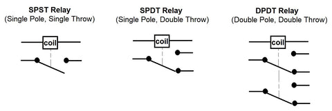
- Single Pole Single Throw (SPST): The simplest relay type with one input and one output. It functions like a basic on/off switch, making or breaking a single circuit. SPST relays are suitable for simple on/off control but cannot reverse polarity.
- Single Pole Double Throw (SPDT): Features one input and two outputs — one normally open (NO) and one normally closed (NC). This configuration allows you to switch between two different circuits or states. SPDT relays are essential for creating bidirectional actuator control.
- Double Pole Double Throw (DPDT): Contains two completely separate SPDT switches operated by a single coil. This allows simultaneous switching of two circuits, making it ideal for reversing polarity to a linear actuator with a single relay.
The contact terminals are labeled based on their default state when the coil is not energized. Normally Closed (NC) contacts are connected when the relay is off and disconnect when energized. Normally Open (NO) contacts are disconnected when the relay is off and connect when energized. The Common (COM) terminal is the pole that switches between NC and NO connections.
Why Use Relays for Linear Actuator Control
Relays solve several critical challenges in actuator control systems that switches alone cannot address. Understanding these advantages helps you design more capable and reliable automation systems.
Electrical Isolation and Protection
The primary benefit of relay control is complete galvanic isolation between your control circuit and the actuator power circuit. When controlling a 12V actuator drawing 10 amps, your relay coil might only draw 50-100 milliamps at 5V. If you attempted to switch 10 amps directly through an Arduino output pin rated for 40 milliamps, you would immediately damage the microcontroller.
This isolation also protects against voltage transients and electromagnetic interference. Linear actuators generate back-EMF (electromotive force) when stopping, which can spike voltages well above the supply voltage. The relay's physical air gap prevents these transients from reaching your control electronics. For feedback actuators and systems using sensitive positioning sensors, this isolation is crucial for reliable operation.
High Current Switching Capability
Industrial and heavy-duty linear actuators can draw significant current, especially during startup and under load. A typical heavy-duty actuator might draw 15-20 amps at 24V, which is far beyond the capability of semiconductor switches in microcontrollers or most transistors without substantial heat sinking.
Relays with properly rated contacts can handle these currents reliably. When selecting relays for actuator control, you'll commonly see ratings like "10A 250V AC / 10A 30V DC" or "16A 250V AC / 16A 30V DC." These ratings indicate the maximum current and voltage the contacts can safely switch. For actuator applications, focus on the DC ratings, as actuators operate on direct current.
Automation and Programmable Control
Unlike mechanical switches that require physical activation, relays enable true automation. You can trigger relay control from virtually any electrical signal source:
- Microcontrollers like Arduino, Raspberry Pi, or ESP32 for programmable logic and IoT integration
- Temperature sensors for climate-responsive ventilation systems
- Proximity or limit switches for automated positioning sequences
- Timers for scheduled operations like automated window openers or solar tracking
- Pressure sensors for hydraulic system alternatives
- Motion detectors for security or access control applications
This programmability transforms simple linear motion into intelligent automation. Combined with the right control logic, relay-controlled actuators can execute complex sequences, respond to multiple inputs, and integrate with larger building automation or industrial control systems.
Controlling Linear Actuators with DPDT Relays
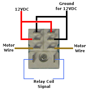
A Double Pole Double Throw (DPDT) relay provides the most compact solution for bidirectional actuator control. With eight total connections — two for the coil, four on the input side, and two on the output side — a single DPDT relay can reverse polarity to extend and retract your actuator.
DPDT Wiring Configuration
There are two primary ways to wire a DPDT relay for actuator control, both achieving the same polarity reversal result:
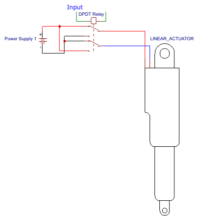
Configuration 1 - Actuator Connected to Input Side: Connect your linear actuator leads to the four input terminals, with positive and negative crossed between the two poles. Connect your power supply positive and negative to the two output terminals. When the coil energizes, it switches which input pair receives positive and negative voltage, reversing the actuator direction.
Configuration 2 - Power Supply Connected to Input Side: Connect your power supply to the four input terminals with positive and negative crossed between poles. Connect the actuator to the two output terminals. This configuration is functionally identical but may be easier to wire depending on your physical layout.
Operational Characteristics and Limitations
With a DPDT relay configuration, you have only two states: coil energized (actuator extends) and coil de-energized (actuator retracts). There is no neutral "off" position where the actuator stops between fully extended and fully retracted positions. This creates several important considerations:
Limit Switch Requirement: Your linear actuator must have internal limit switches that automatically cut power when reaching full extension or retraction. Without limit switches, energizing the coil after the actuator reaches its mechanical limit would stall the motor, drawing locked-rotor current that can quickly overheat and damage the actuator. All FIRGELLI actuators include internal limit switches as standard for this exact reason.
Fail-Safe Positioning: Wire your NC (normally closed) connections to correspond with your desired safe position if control power fails. If it's critical that your actuator defaults to the retracted position during power loss, ensure retraction occurs when the coil is de-energized. This prevents unexpected movement during system startup or control failures.
Application Suitability: DPDT single-relay control works well for applications requiring only fully extended or fully retracted positions — things like pop-up TV lifts, automated gates, or access panels. However, if you need to stop the actuator at intermediate positions, you'll need to use a two-relay configuration instead.
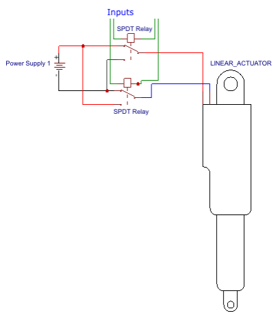
Controlling Linear Actuators with Two SPDT Relays
For applications requiring the ability to stop your actuator at any position along its stroke, a two-relay configuration using SPDT (Single Pole Double Throw) relays provides the necessary control. This setup adds a true "off" state between extension and retraction, giving you three control conditions instead of two.
Dual SPDT Wiring Configuration
The two-relay configuration uses one SPDT relay for each actuator lead, creating an H-bridge switching arrangement:
Relay 1 (Positive Side): The common terminal connects to the positive output of your power supply. The NO terminal connects to one actuator lead. The NC terminal connects to ground.
Relay 2 (Negative Side): The common terminal connects to the negative output (ground) of your power supply. The NO terminal connects to the other actuator lead. The NC terminal connects to ground.
In the neutral state with both coils de-energized, both actuator leads connect to ground through the NC contacts, effectively shorting the motor and providing dynamic braking. This prevents the actuator from drifting under load.
Three-State Operation
This configuration provides three distinct operating modes:
Extend: Energize Relay 1 only. This connects positive voltage to actuator lead 1 and ground to actuator lead 2, driving the motor in one direction.
Retract: Energize Relay 2 only. This connects ground to actuator lead 1 and positive voltage to actuator lead 2, reversing polarity and driving the motor in the opposite direction.
Stop: De-energize both relays. Both actuator leads connect to ground through NC contacts, stopping the motor and providing holding resistance. This is your neutral position where the actuator remains stationary at any point in its stroke.
Critical Interlock Requirements
A crucial safety consideration with two-relay control is preventing simultaneous energization of both relays. If both coils energize at the same time, you create a direct short circuit from positive to ground through the relay contacts, bypassing the actuator entirely. This will instantly damage the relays and potentially the power supply.
Your control logic must implement interlocking to prevent this condition:
- Software Interlocks: If controlling relays with a microcontroller, program logic that prohibits both outputs from going high simultaneously. Include a brief delay (50-100 milliseconds) between turning one relay off and turning the other on to allow contacts to fully settle.
- Hardware Interlocks: For systems without microcontroller control, use mechanical interlocking switches or relay modules with built-in interlock circuitry.
- Relay Modules: Pre-made relay modules designed for motor control often include interlock protection and may simplify your implementation, especially for applications controlling multiple actuators.
Advantages Over Single DPDT Configuration
While requiring two relays instead of one, this configuration offers significant benefits:
- Precise positioning at any point along the stroke by stopping on command
- Dynamic braking when stopped prevents load-induced drift
- Better suited for feedback actuators where position sensing enables closed-loop control
- More flexible for applications like adjustable standing desks or variable window positioning
- Fail-safe operation with both actuator leads grounded in the de-energized state
Selecting the Right Relay for Your Application
Choosing an appropriate relay involves matching several specifications to your actuator and control system requirements. Under-specifying any parameter can lead to premature relay failure, unreliable operation, or safety hazards.
Contact Current and Voltage Ratings
The most critical specification is the relay's contact rating, typically stated as maximum current and voltage for both AC and DC loads. For linear actuator applications, focus on DC ratings, which are generally lower than AC ratings for the same relay due to arc suppression challenges with DC.
Common relay ratings you'll encounter include:
- 10A 250V AC / 10A 30V DC: Suitable for most 12V actuators drawing up to 10 amps, including many standard and track actuators
- 16A 250V AC / 16A 30V DC: Better choice for larger 12V actuators or 24V systems with moderate current draw
- 30A 250V AC / 30A 30V DC: Required for heavy-duty industrial actuators or multiple actuators on a single relay
Always select a relay rated for at least 25-50% more current than your actuator's maximum draw. This derating accounts for contact degradation over time, inrush current during startup, and provides margin for reliability. Check your actuator's specification sheet for current draw — FIRGELLI actuators typically range from 2-3 amps for micro actuators to 15+ amps for heavy-duty models.
Coil Voltage and Power Requirements
The relay coil must be compatible with your control circuit voltage. Common coil voltages include 5V, 12V, and 24V. The coil voltage should match your control signal source:
- 5V coils: Compatible with Arduino, Raspberry Pi, and most logic-level microcontrollers with appropriate driver circuitry
- 12V coils: Can be powered from the same supply as 12V actuators, simplifying system design
- 24V coils: Appropriate for industrial control systems and 24V actuator applications
Note that most microcontroller outputs cannot drive relay coils directly — the current requirement of 50-100mA exceeds typical GPIO current limits. You'll need a transistor driver circuit or use a relay module with integrated driver electronics. Relay modules often include flyback diode protection, LED indicators, and multiple relay channels on a single board.
Contact Type and Life Expectancy
Relays use different contact materials and designs that affect performance and longevity:
Contact Material: Silver alloy contacts are common and provide good conductivity with reasonable life expectancy. Gold-plated contacts offer better resistance to corrosion and are preferred for low-current signal switching, but they're generally not necessary for actuator power switching.
Mechanical Life: Specified as the number of operations without electrical load, typically millions of cycles. This matters less than electrical life for most applications.
Electrical Life: The number of switching operations under rated load, usually 100,000 to 500,000 cycles. Higher-quality relays with robust contacts and arc suppression features provide longer electrical life. For frequently cycling applications, this specification is critical.
Arc Suppression: DC switching creates arcing between contacts that can erode contact surfaces. Some relays include magnetic blowout features or bifurcated contacts to minimize arcing. For inductive loads like actuators, consider adding external arc suppression components like snubber diodes or RC networks across the contacts.
Mounting Style and Form Factor
Relays come in several mounting configurations:
- PCB Mount: Designed to solder directly onto circuit boards, available in through-hole or surface-mount packages
- Socket Mount: Plug into separate relay sockets, allowing easy replacement without soldering
- Panel Mount: Designed for mounting in enclosures with screw terminals for all connections
- DIN Rail Mount: Industrial standard mounting for control panels and electrical enclosures
For prototyping and DIY projects, relay modules with screw terminals and built-in driver circuits are often the most practical choice. These modules handle the driver transistor, flyback diode, and provide clear terminal labeling.
Practical Implementation Considerations
Successfully implementing relay control involves more than just wiring the components together. Several practical considerations can make the difference between a reliable system and one plagued by intermittent failures.
Wire Sizing and Connections
Use appropriately sized wire for the actuator power circuit. For 12V systems drawing 10 amps, 16 AWG wire is adequate for runs up to 10 feet. For longer distances or higher currents, use heavier gauge wire to minimize voltage drop. A 10% voltage drop can reduce actuator force by 20% or more due to the relationship between voltage and motor torque.
Ensure all connections are mechanically secure. Loose screw terminals are a common failure point causing intermittent operation. Use ring or spade terminals crimped to wire ends for screw terminal connections rather than inserting bare wire. For applications subject to vibration, add split lock washers under screw terminals.
Flyback Diode Protection
Linear actuators are inductive loads that generate voltage spikes when power is interrupted. These back-EMF spikes can reach several hundred volts and damage relay contacts or the coil driver circuit. Add flyback (freewheeling) diodes across both the relay coil and across the actuator leads.
For coil protection, use a diode rated for the coil current with a reverse voltage rating of at least twice the supply voltage. The diode connects in parallel with the coil, cathode (striped end) to the positive coil terminal. This provides a path for coil current when the driving transistor switches off.
For actuator protection, particularly in the two-relay configuration, consider adding diodes in an H-bridge arrangement or use a single diode across the actuator with a series resistor to provide rapid but controlled energy dissipation.
Control Signal and Timing Considerations
Relay contacts don't switch instantaneously — typical operate time is 5-15 milliseconds and release time is 3-10 milliseconds. When switching between extend and retract, include a delay in your control logic to ensure contacts have fully transitioned before changing state. A 50-100 millisecond delay prevents damage from momentary short circuits during switching.
For Arduino or microcontroller control, implement debouncing on input buttons or switches to prevent multiple rapid relay activations from a single button press. Also consider implementing soft-start sequencing if controlling multiple actuators — energizing all relays simultaneously can create large inrush current spikes.
Feedback and Position Sensing Integration
While basic relay control provides bidirectional movement, integrating position feedback actuators with relay control requires additional consideration. The actuator's feedback signal (typically a potentiometer output) must be monitored by your control system, which then determines when to de-energize relays to stop at the desired position.
This requires an analog-to-digital converter (ADC) to read the feedback signal and control logic to compare actual position against target position. The two-relay SPDT configuration is essential for feedback control, as you need the ability to stop the actuator at arbitrary positions. Simple DPDT control only works for end-position sensing.
Limitations and When to Consider Alternatives
While relay control is robust and reliable for many applications, it has inherent limitations that may make alternatives more suitable for certain requirements.
Key Limitations of Relay Control
No Speed Control: Relays are on/off switches and cannot vary actuator speed. The actuator operates at full speed whenever power is applied. If your application requires variable speed for smooth motion or reduced noise, you'll need a motor controller with PWM (pulse width modulation) capability instead.
Multiple Actuator Complexity: Controlling multiple actuators independently requires dedicated relays for each actuator. A system with four independent actuators needs eight SPDT relays (or four DPDT relays), plus the associated wiring and control logic. This quickly becomes cumbersome compared to a programmable motor controller.
Limited Feedback Utilization: While you can use feedback signals to stop at positions, relay control doesn't provide the precision of closed-loop motor control. There's always a stopping delay as the actuator coasts after relay de-energization, and you cannot implement PID control or other advanced positioning algorithms.
Mechanical Wear: Relay contacts physically move with each operation, subjecting them to mechanical wear and eventual failure. High-cycle applications may require periodic relay replacement. Solid-state alternatives have no moving parts and much longer lifespans in frequent-switching applications.
Switching Noise: The physical contact closure creates electrical noise that can interfere with sensitive electronics. While isolation helps, extremely noise-sensitive applications may benefit from solid-state switching.
Alternative Control Methods
For applications where relay limitations are problematic, consider these alternatives:
Motor Controllers and H-Bridges: Electronic motor controllers using MOSFETs or IGBTs provide variable speed control, rapid switching without mechanical wear, and can drive high currents efficiently. Many include built-in microcontrollers that handle direction, speed, and position control through simple serial commands. FIRGELLI offers control boxes that provide sophisticated control while simplifying implementation.
Solid-State Relays (SSR): Use semiconductor switching instead of mechanical contacts, offering silent operation, no contact bounce, longer life in high-cycle applications, and faster switching. However, SSRs typically have higher on-state voltage drop and require heat sinking for high-current loads.
Integrated Control Systems: For complex multi-actuator applications, integrated control systems with remote control provide synchronized motion, programmable sequences, and user-friendly operation without requiring custom circuit design.
Troubleshooting Common Issues
When your relay-controlled actuator system doesn't work as expected, systematic troubleshooting can quickly identify the problem.
Actuator Not Moving
If your actuator doesn't respond when you expect it to extend or retract:
- Verify power supply voltage with a multimeter — low voltage under load indicates inadequate supply capacity
- Check that relay coil is receiving control voltage — most relay modules have LED indicators
- Listen for relay click when energizing — if no click, check coil voltage and driver circuit
- Measure voltage at actuator terminals when relay is energized — should read full supply voltage
- Verify actuator hasn't reached limit and internal limit switch has cut power
- Check all wire connections, especially screw terminals which can loosen over time
Intermittent Operation
If the actuator works sometimes but not consistently:
- Inspect relay contacts for pitting or corrosion — visible damage indicates replacement needed
- Verify all connections are tight and not subject to vibration loosening
- Check for voltage drops in long wire runs, especially under load
- Ensure relay is not operating at or above its rated current — overloaded relays fail intermittently
- Test with a known good relay to rule out relay failure
Blown Fuses or Tripped Protection
If circuit protection trips when operating the system:
- Check for short circuits in wiring, especially where insulation may be damaged
- Verify both relays aren't energizing simultaneously in two-relay configurations
- Ensure actuator isn't mechanically jammed, causing locked-rotor current draw
- Confirm relay current rating exceeds actuator requirements
Relay Chattering
If the relay rapidly cycles on and off:
- Power supply may be inadequate — relay coil draw is dropping supply voltage, causing de-energization
- Control signal may be floating or noisy — ensure clean control signals with proper pull-up/pull-down
- Flyback diode across coil may be reversed or missing, causing voltage spikes that disrupt control circuit
Conclusion
Relay-based control of linear actuators provides a reliable, cost-effective foundation for automation projects ranging from simple DIY applications to industrial systems. By understanding relay fundamentals, selecting appropriate configurations, and implementing proper protection and control logic, you can design robust actuator control systems that safely operate for years.
The choice between single DPDT and dual SPDT relay configurations depends on your application requirements — DPDT for simple two-position control, and dual SPDT when you need the ability to stop at intermediate positions. Both approaches provide the critical electrical isolation that protects control electronics while switching high-power actuator loads.
While relay control has limitations in speed control and advanced positioning, it excels in applications requiring straightforward bidirectional motion with reliable operation. For more sophisticated control requirements, consider graduated to electronic motor controllers or integrated control systems that build upon these relay control fundamentals.
Frequently Asked Questions
What type of relay do I need to control a linear actuator?
You need either a DPDT (Double Pole Double Throw) relay or two SPDT (Single Pole Double Throw) relays. A single DP


