Sizing an aperture wrong costs you light, resolution, and signal quality — and the math changes depending on whether your aperture is circular, rectangular, elliptical, or defined by an f-number. Use this Aperture Area Interactive Calculator to calculate cross-sectional aperture area using diameter, radius, width and height, semi-axes, or focal length and f-number. It matters across astronomical telescopes, camera lens design, radar antenna engineering, and fiber optic coupling. This page includes the governing formulas, a worked multi-telescope example, theory on diffraction limits and f-numbers, and a full FAQ.
What is aperture area?
Aperture area is the cross-sectional area of the opening through which light, radiation, or wave energy passes in an optical or electromagnetic system. A larger aperture area collects more energy — more light for a telescope, more signal for an antenna.
Simple Explanation
Think of aperture area like the opening of a bucket catching rain: a wider bucket catches more water in the same amount of time. In optics, a wider aperture catches more light, which makes images brighter and lets you resolve finer detail. The shape of that opening — circular, rectangular, or elliptical — determines which formula you use to calculate its area.
📐 Browse all 1000+ Interactive Calculators
How to Use This Calculator
- Select your Calculation Mode from the dropdown — choose circular (from diameter or radius), diameter from area, rectangular, elliptical, or f-number based.
- Enter the required dimension(s) for your selected mode — diameter, radius, width and height, semi-axes, or f-number and focal length.
- Optionally click Try Example to load sample values and see a working result.
- Click Calculate to see your result.
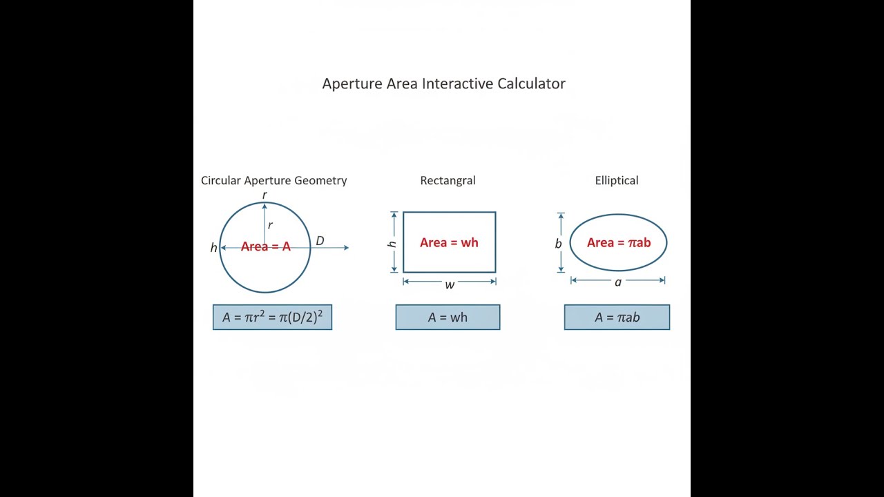
Aperture Geometry Diagram

Interactive Aperture Area Calculator
Aperture Area Interactive Visualizer
Visualize how aperture geometry affects light-gathering area across circular, rectangular, and elliptical shapes. See real-time calculations for diameter, area, and perimeter as you adjust dimensions.
AREA
5027
PERIMETER
251
EFFICIENCY
78.5%
FIRGELLI Automations — Interactive Engineering Calculators
Governing Equations
Use the formula below to calculate aperture area for each supported aperture shape.
Circular Aperture Area
A = π r² or A = π (D/2)²
A = Aperture area (mm², m²)
r = Radius (mm, m)
D = Diameter (mm, m)
π ≈ 3.14159
Diameter from Area
D = 2√(A/π)
This inverts the area equation to solve for diameter when aperture area is known.
Rectangular Aperture Area
A = w × h
w = Width (mm, m)
h = Height (mm, m)
Elliptical Aperture Area
A = π a b
a = Semi-major axis (mm, m)
b = Semi-minor axis (mm, m)
f-number and Entrance Pupil Diameter
D = f / N
f = Focal length (mm, m)
N = f-number (dimensionless)
D = Entrance pupil diameter (mm, m)
The effective aperture area is then A = π (D/2)²
Simple Example
Circular aperture from diameter — mode: Circular Aperture from Diameter
- Input: Diameter = 50 mm
- Radius = 25 mm
- Area = π × 25² = 1963.495 mm²
- Circumference = π × 50 = 157.080 mm
Theory & Practical Applications
Aperture area fundamentally determines the light-gathering power and diffraction-limited resolution of optical and electromagnetic systems. In astronomical telescopes, doubling the aperture diameter quadruples the collecting area, enabling detection of objects four times fainter — a critical relationship that drives mirror fabrication costs exponentially. In camera systems, aperture area directly controls depth of field through the f-number relationship, with photographers exploiting this to isolate subjects at f/1.4 (large aperture, shallow depth) or maximize focus range at f/16 (small aperture). Radio frequency engineers design phased array antennas with effective apertures exceeding physical dimensions through constructive interference, achieving gain proportional to the ratio of effective aperture area to wavelength squared.
Diffraction-Limited Resolution and the Airy Disk
The angular resolution limit θ of a circular aperture arises from the Airy diffraction pattern, where the first minimum occurs at θ = 1.22 λ/D radians. This means that for visible light (λ ≈ 550 nm) passing through a 100 mm diameter telescope aperture, the minimum resolvable angular separation is approximately 1.38 arcseconds. Astronomical observatories operating at this limit must account for atmospheric turbulence (seeing), which typically degrades ground-based resolution to 0.5–2 arcseconds regardless of aperture size above 20 cm diameter.
Adaptive optics systems compensate by measuring wavefront distortions at rates exceeding 1 kHz and applying corrections via deformable mirrors with actuator densities matching the aperture area divided by the Fried parameter r₀, typically 10–20 cm at visible wavelengths.
In microscopy, numerical aperture NA = n sin(θ) replaces simple aperture diameter, where n is the refractive index of the immersion medium and θ is the half-angle of the collection cone. Oil immersion objectives (n = 1.518) achieve NA values up to 1.45, enabling lateral resolution down to λ/(2NA) ≈ 190 nm at λ = 550 nm. The effective aperture area in the object plane scales as π(NA/M)² where M is magnification, creating a fundamental tradeoff between resolution and field of view that cannot be circumvented by lens design alone.
Light-Gathering Power and Photon Flux
Photon flux Φ incident on a detector scales linearly with aperture area for extended sources (planets, nebulae) but remains constant for point sources (stars) when aperture increases while maintaining constant f-number. This non-intuitive result arises because larger apertures collect more photons but spread them over proportionally larger image areas. For a star of apparent magnitude m viewed through aperture area A, the detected photon rate is Φ = (2.52 × 10¹⁰) × A × 10^(-0.4m) photons/second/m² at λ = 550 nm, assuming perfect quantum efficiency. Increasing aperture diameter from 200 mm to 400 mm quadruples collection area, enabling detection of stars 1.5 magnitudes fainter in the same integration time.
Charge-coupled device (CCD) cameras with pixel sizes p must satisfy the Nyquist criterion p ≤ λf/(2D) to avoid undersampling the Airy disk, where f is the focal length. For an f/8 system (f = 8D) at λ = 550 nm, this yields p ≤ 2.2 μm. Modern CMOS sensors with 1.4 μm pixels deliberately oversample to enable subpixel centroiding, achieving astrometric precision better than 0.01 pixels through weighted centroid algorithms when signal-to-noise ratio exceeds 100.
Rectangular and Non-Circular Apertures
Rectangular apertures produce separable diffraction patterns along each axis, with the first nulls occurring at angles θ_x = λ/w and θ_y = λ/h. Slit apertures in spectrographs exploit this asymmetry, using narrow widths (10–100 μm) for high spectral resolution while maintaining adequate height (several mm) for sufficient light collection. The spectral resolving power R = λ/Δλ relates to slit width w and grating parameters through R = (m N) / (w/f_camera), where m is diffraction order and N is the number of illuminated grating lines. Professional echelle spectrographs achieve R exceeding 100,000 by using 50 μm slits with f/8 camera optics and cross-dispersion to separate overlapping orders.
Annular apertures, common in Cassegrain and Maksutov telescope designs, have central obscurations that reduce effective collecting area while increasing the Airy disk diameter and strengthening diffraction rings. For a central obscuration ratio ε (diameter of secondary divided by primary), the effective collecting area reduces to A_eff = π(D²/4)(1 - ε²). A typical Schmidt-Cassegrain with ε = 0.33 loses 11% of light-gathering power but gains compactness and reduced spherical aberration through the optical design. The Strehl ratio quantifying image quality degrades from unity by approximately 1 - ε² for moderate obscurations below 0.4.
f-number, Aperture Stop, and Vignetting
The f-number N = f/D relates focal length to entrance pupil diameter, controlling not only exposure (proportional to 1/N²) but also depth of field and diffraction blur. Photographers distinguish between the physical aperture (iris diaphragm setting) and the effective aperture (entrance pupil as seen from object space), which differ when front lens elements magnify or reduce the aperture's apparent size. Telephoto lenses often use internal focusing that changes effective focal length by 5–10% across the focus range, causing the effective f-number to vary even when the iris remains fixed.
Vignetting reduces effective aperture area for off-axis field angles, with cos⁴(θ) natural falloff compounded by mechanical obstruction from lens barrels and filter threads. Wide-angle lenses at f/2.8 commonly exhibit 2–3 stops of corner darkening at maximum aperture, correctable through digital processing but irreversible for shot noise. Lens designers minimize vignetting by increasing front element diameter beyond the paraxial aperture requirement, adding cost and weight — a 24mm f/1.4 lens may use an 82mm filter thread to maintain even illumination across a 35mm sensor's ±21° diagonal field angle.
Worked Example: Astronomical Telescope Light-Gathering and Resolution
Problem: An amateur astronomer is comparing two Newtonian reflecting telescopes for deep-sky astrophotography. Telescope A has a 203 mm (8-inch) aperture with a focal length of 1000 mm. Telescope B has a 305 mm (12-inch) aperture with a focal length of 1500 mm. Both will be used with a monochrome CCD camera having 5.4 μm pixels. Calculate: (a) the aperture areas and light-gathering power ratio, (b) the diffraction-limited angular resolution at λ = 550 nm, (c) the f-number for each system, (d) the Airy disk diameter in the focal plane, and (e) whether the pixel size adequately samples the Airy disk for each telescope.
Solution:
(a) Aperture Areas and Light-Gathering Ratio:
For Telescope A with diameter D_A = 203 mm = 0.203 m:
Radius r_A = 0.203 / 2 = 0.1015 m
Area A_A = π r_A² = π (0.1015)² = 0.03237 m²
For Telescope B with diameter D_B = 305 mm = 0.305 m:
Radius r_B = 0.305 / 2 = 0.1525 m
Area A_B = π r_B² = π (0.1525)² = 0.07310 m²
Light-gathering power ratio:
Ratio = A_B / A_A = 0.07310 / 0.03237 = 2.258
Telescope B gathers approximately 2.26 times more light than Telescope A, corresponding to a gain of 0.88 magnitudes in limiting brightness (since 2.512^0.88 ≈ 2.26).
(b) Diffraction-Limited Angular Resolution:
The Rayleigh criterion for angular resolution is θ = 1.22 λ/D radians, where λ = 550 nm = 550 × 10⁻⁹ m.
For Telescope A:
θ_A = 1.22 × (550 × 10⁻⁹) / 0.203 = 3.306 × 10⁻⁶ radians
Converting to arcseconds: θ_A = 3.306 × 10⁻⁶ × (206265) = 0.682 arcseconds
For Telescope B:
—_B = 1.22 × (550 × 10⁻⁹) / 0.305 = 2.200 × 10⁻⁶ radians
Converting to arcseconds: θ_B = 2.200 × 10⁻⁶ × (206265) = 0.454 arcseconds
Telescope B provides 50% better angular resolution, though atmospheric seeing typically limits ground-based performance to 1–2 arcseconds.
(c) f-number Calculation:
The f-number N = f / D, where f is focal length.
For Telescope A:
N_A = 1000 mm / 203 mm = 4.93 ≈ f/4.9
For Telescope B:
N_B = 1500 mm / 305 mm = 4.92 ≈ f/4.9
Both systems have nearly identical f-numbers, meaning they provide the same surface brightness for extended objects and identical exposure times for equivalent detector sensitivity, despite the difference in absolute light-gathering power.
(d) Airy Disk Diameter in Focal Plane:
The Airy disk diameter (first dark ring) is d = 2.44 λ f / D = 2.44 λ N.
For Telescope A:
d_A = 2.44 × (550 × 10⁻⁶ mm) × 4.93 = 6.62 μm
For Telescope B:
d_B = 2.44 × (550 × 10⁻⁶ mm) × 4.92 = 6.60 μm
The Airy disk diameters are essentially identical because both systems have the same f-number, even though their absolute apertures differ.
(e) Nyquist Sampling Assessment:
The Nyquist criterion requires at least two pixels across the Airy disk radius, or pixel size p ≤ d/4.88 (where d is the Airy disk diameter to first minimum).
For both telescopes:
p_max = 6.61 μm / 4.88 = 1.35 μm
Actual pixel size = 5.4 μm
Sampling ratio = 5.4 / 1.35 = 4.0
The 5.4 μm pixels severely undersample the Airy disk by a factor of 4, meaning the camera cannot resolve the full diffraction-limited detail either telescope can deliver. Each pixel spans approximately 4 Airy disk radii, losing information. To achieve proper sampling, this camera would require a focal reducer or Barlow lens to adjust the effective focal length, or alternatively, a camera with smaller pixels (1.5 μm or less) should be used. This underscores a common astrophotography challenge: matching detector pixel size to telescope optical characteristics requires careful system integration beyond simply selecting based on aperture area alone.
For more optical system calculations, visit the FIRGELLI Engineering Calculator Hub.
Frequently Asked Questions
▼ How does aperture area affect camera exposure time?
▼ Why do telescopes use mirrors instead of lenses for large apertures?
▼ What is the difference between physical aperture and effective aperture?
▼ How does aperture shape affect image quality beyond just area?
▼ Can adaptive optics overcome diffraction limits set by aperture area?
▼ Why does aperture area matter differently for coherent versus incoherent light sources?
Free Engineering Calculators
Explore our complete library of free engineering and physics calculators.
Browse All Calculators →🔗 Explore More Free Engineering Calculators
About the Author
Robbie Dickson — Chief Engineer & Founder, FIRGELLI Automations
Robbie Dickson brings over two decades of engineering expertise to FIRGELLI Automations. With a distinguished career at Rolls-Royce, BMW, and Ford, he has deep expertise in mechanical systems, actuator technology, and precision engineering.
Need to implement these calculations?
Explore the precision-engineered motion control solutions used by top engineers.


