Designing a lighting system without understanding the relationship between intensity, flux, and surface illuminance leads to under-lit spaces, wasted energy, and failed compliance checks. Use this Photometric Lux Candela Lumen Calculator to convert between lux, candela, and lumens using inputs like distance, solid angle, surface area, and incidence angle. It matters in architectural lighting, machine vision, photography, and any application where light levels directly affect performance or safety. This page includes the core formulas, a worked gallery lighting example, application theory, and an FAQ covering common design pitfalls.
What is photometric conversion?
Photometric conversion is the process of calculating how light intensity (candela), total light output (lumens), and surface brightness (lux) relate to each other. These 3 units describe different aspects of the same light source, and knowing one lets you find the others when you also know the geometry — distance, angle, or area.
Simple Explanation
Think of lumens as the total amount of water coming out of a hose, candela as how hard that water hits a single spot, and lux as how wet a surface gets per square meter. A tight nozzle (narrow beam) concentrates the same water into a smaller area — higher lux, higher candela, same lumens. Spread it wide and the surface gets less wet per square meter, even though the water flow hasn't changed.
📐 Browse all 1000+ Interactive Calculators
Photometric Quantities Diagram

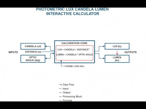
How to Use This Calculator
- Select a calculation mode from the dropdown — choose what you want to solve for (lux, candela, lumens, or distance).
- Enter the known values into the visible input fields — luminous intensity, illuminance, distance, solid angle, or surface area depending on the selected mode.
- Set the incidence angle if your light hits the surface at an angle other than perpendicular (enter 0 for straight-on illumination).
- Click Calculate to see your result.
Photometric Interactive Calculator
Photometric Lux Candela Lumen Interactive Visualizer
Watch how luminous intensity (candela), surface illuminance (lux), and distance interact through the inverse square law. Adjust parameters to see real-time photometric calculations with visual beam patterns and illumination zones.
ILLUMINANCE
56 lux
TOTAL LUMENS
524 lm
SOLID ANGLE
1.05 sr
FIRGELLI Automations — Interactive Engineering Calculators
Equations & Formulas
Use the formula below to calculate illuminance from a point source at a known distance and angle.
Inverse Square Law (Point Source Illuminance)
E = (I × cos θ) / d²
E = Illuminance (lux or lm/m²)
I = Luminous intensity (candela, cd)
θ = Angle of incidence (degrees or radians)
d = Distance from source (meters)
Use the formula below to calculate luminous flux from intensity and beam solid angle.
Luminous Flux from Intensity
Φ = I × Ω
Φ = Luminous flux (lumens, lm)
I = Luminous intensity (candela, cd)
Ω = Solid angle (steradians, sr)
For a full sphere: Ω = 4π ≈ 12.566 sr
Use the formula below to calculate average illuminance across a surface from total flux and area.
Average Illuminance from Flux
Eavg = Φ / A
Eavg = Average illuminance (lux)
Φ = Total luminous flux (lumens)
A = Surface area (square meters)
Assumes uniform flux distribution over the surface
Use the formula below to calculate the solid angle subtended by a cone beam from its half-angle.
Solid Angle of a Cone
Ω = 2π(1 - cos α)
Ω = Solid angle (steradians)
α = Half-angle of cone (radians)
For small angles: Ω ≈ π(α²) when α is in radians
Use the formula below to calculate average luminous intensity from flux emitted within a known solid angle.
Candela from Known Flux Distribution
I = Φ / Ω
I = Average luminous intensity (candela)
Φ = Luminous flux within solid angle (lumens)
Ω = Solid angle of emission (steradians)
Valid for uniform intensity distribution within Ω
Simple Example
A 100 cd spotlight illuminates a surface directly below it (0° incidence angle) at a distance of 2 m.
E = (100 × cos 0°) / 2² = 100 / 4 = 25 lux
Double the distance to 4 m and illuminance drops to 100 / 16 = 6.25 lux — one quarter the original value. That's the inverse square law in action.
Theory & Engineering Applications
Photometry forms the foundation of quantitative lighting design by measuring light in units that correspond to human visual perception. Unlike radiometry, which measures electromagnetic power across all wavelengths, photometry weights measurements according to the photopic luminosity function V(λ), which peaks at 555 nanometers (green light) where the human eye exhibits maximum sensitivity. This physiological weighting makes photometric quantities essential for applications where human vision is the primary concern — architectural lighting, display design, safety illumination, and visual task optimization.
Fundamental Photometric Quantities
The candela (cd), one of the seven SI base units, defines luminous intensity as the luminous power per unit solid angle emitted by a point source in a particular direction. Historically defined using a standard candle, the candela is now defined precisely: a monochromatic source emitting radiation at 540 × 10¹² Hz (555 nm wavelength) with a radiant intensity of 1/683 watt per steradian has a luminous intensity of one candela. This definition anchors all other photometric units.
Luminous flux, measured in lumens (lm), represents the total quantity of visible light emitted by a source in all directions. A source emitting uniformly in all directions (isotropic source) with an intensity of one candela produces a total flux of 4π lumens, since a complete sphere subtends a solid angle of 4π steradians. Most real sources exhibit directional emission patterns, requiring integration of intensity over the entire sphere to determine total flux. LED manufacturers specify luminous efficacy in lumens per watt, quantifying how efficiently electrical power converts to visible light.
Illuminance, measured in lux (lx) or equivalently lumens per square meter, quantifies the luminous flux incident on a surface per unit area. One lux equals one lumen distributed uniformly over one square meter. This metric directly correlates with perceived brightness on illuminated surfaces and forms the basis for lighting standards. Building codes typically specify minimum illuminance levels: 500 lux for detailed office work, 200 lux for general corridor lighting, and as low as 50 lux for emergency egress lighting. Understanding the distinction between luminance (brightness of a light source or reflecting surface) and illuminance (light falling on a surface) prevents common design errors.
The Inverse Square Law and Distance Effects
For point sources or sources where the distance greatly exceeds the source dimensions, illuminance decreases with the square of distance according to E = I/d². This relationship, fundamental to lighting design, means doubling the distance from a source reduces illuminance to one-quarter the original value. At three times the distance, illuminance drops to one-ninth. This rapid falloff profoundly impacts practical lighting: a desk lamp effective at 0.5 meters becomes nearly useless at 2 meters, not because it produces less light, but because the same flux spreads over sixteen times the area.
The cosine law modifies this relationship when light strikes a surface at an oblique angle. The effective illuminance becomes E = (I × cos θ)/d², where θ represents the angle between the incident light direction and the surface normal. At 60 degrees incidence, the cosine factor of 0.5 cuts illuminance in half compared to perpendicular incidence. This effect explains why surfaces facing away from light sources appear dimmer even at equal distances — a critical consideration in architectural lighting where wall washing and uniform illumination require careful fixture placement and aiming angles.
Solid Angles and Beam Optics
Solid angle, measured in steradians (sr), extends the concept of planar angles into three dimensions. Just as a radian measures arc length divided by radius, a steradian measures projected area divided by the square of radius. A complete sphere subtends 4π ≈ 12.566 steradians at its center. Practical light sources rarely emit uniformly across this full sphere; reflectors, lenses, and LED die geometry concentrate flux into specific solid angles.
A narrow spotlight with a 10-degree half-angle cone (20-degree full beam width) covers a solid angle of approximately Ω = 2π(1 - cos 10°) ≈ 0.0239 sr, representing only 0.19% of a full sphere. If this spotlight produces 1000 lumens total flux, its average intensity within the beam is I = 1000/0.0239 ≈ 41,841 candela — an extraordinarily bright source within that narrow cone. This concentration principle enables theatrical spotlights to project visible beams through haze and architectural fixtures to create dramatic accent lighting from modest lumen packages.
The small-angle approximation Ω ≈ π(α²) simplifies calculations for narrow beams where the half-angle α (in radians) is less than about 0.3 radians (17 degrees). For a 5-degree half-angle (0.0873 radians), this approximation gives Ω ≈ 0.0239 sr, matching the exact calculation. Beyond 20 degrees, errors become significant, requiring the full formula. Understanding when approximations apply accelerates iterative design while maintaining accuracy.
Real-World Complications and Limitations
Actual light sources violate the point-source assumption at close range. When the distance to an illuminated surface is less than five times the maximum source dimension, the inverse square law produces errors exceeding 10%. Fluorescent tubes, LED panels, and architectural cove lighting require near-field calculations using integration over the extended source area or empirical measurement. Some lighting design software packages include near-field models, but many calculations revert to measurements or computational photometry for accuracy.
Surface reflectance and material properties dramatically affect practical illuminance. The calculations presented here compute incident illuminance — the flux arriving at a surface. The luminance (perceived brightness) depends on the surface's reflectance and bidirectional reflectance distribution function (BRDF). A white matte surface with 90% reflectance appears much brighter than a black matte surface with 5% reflectance under identical illuminance. Specular surfaces introduce view-angle dependencies, and many materials exhibit complex combinations of diffuse and specular reflection requiring measurement or sophisticated models.
Worked Example: Gallery Lighting Design
An art gallery curator needs to illuminate a painting measuring 1.2 meters × 0.9 meters with an average illuminance of 300 lux, a common target for artwork that balances visibility with preservation (higher illuminance accelerates fading). The available track-mounted spotlight produces 2400 lumens and incorporates a reflector creating a 30-degree half-angle cone beam (60-degree full width). We must determine the required mounting distance and verify the intensity distribution.
Step 1: Calculate the beam solid angle.
Half-angle α = 30° = 0.5236 radians
Ω = 2π(1 - cos 0.5236) = 2π(1 - 0.8660) = 2π(0.1340) = 0.8418 steradians
Step 2: Determine average luminous intensity within the beam.
I = Φ / Ω = 2400 lm / 0.8418 sr = 2850.9 candela
Step 3: Calculate distance for 300 lux at the center of the beam (perpendicular incidence, cos θ = 1).
E = I / d²
300 = 2850.9 / d²
d² = 2850.9 / 300 = 9.503
d = 3.083 meters
Step 4: Verify beam coverage at calculated distance.
At distance d = 3.083 m, the beam radius is r = d × tan(30°) = 3.083 × 0.5774 = 1.780 meters. The beam diameter of 3.560 meters easily covers the 1.2-meter painting width, but much flux falls outside the target area. This represents inefficient use of luminaire output.
Step 5: Calculate illuminated area and average illuminance over full beam.
Beam area at painting distance: A = πr² = π(1.780)² = 9.95 m²
Average illuminance over beam area: E_avg = 2400 lm / 9.95 m² = 241.2 lux
Step 6: Assess design implications.
The calculation reveals a fundamental trade-off: achieving 300 lux at the beam center (where intensity peaks) results in substantial light spillage beyond the 1.08 m² painting area. The painting receives approximately 260 lumens (1.08 m² × 241 lux), while 2140 lumens illuminate the surrounding wall. A narrower beam angle (smaller solid angle, higher intensity) would improve efficiency but requires greater candela and might exceed the painting's photochemical damage threshold.
Alternative approaches include moving the fixture closer (reducing distance to 2.0 m would increase illuminance by factor of (3.083/2.0)² = 2.37) or selecting a fixture with adjustable beam optics to match the target better. This example demonstrates why professional lighting design requires iterative optimization considering luminaire photometry, mounting constraints, target geometry, uniformity requirements, and efficiency. Simple calculations provide starting points, but refined designs often need photometric software or empirical adjustment during installation.
Applications Across Industries
Architectural lighting design relies on photometric calculations to meet building codes, optimize energy efficiency, and create desired visual atmospheres. The Illuminating Engineering Society (IES) publishes recommended illuminance levels for hundreds of applications: 750 lux for surgical tasks, 300-500 lux for general office work, 150 lux for lobbies and corridors. Designers use these targets with fixture photometric data to determine spacing, mounting heights, and wattage requirements. Daylighting calculations integrate photometric principles with solar geometry and window transmission to balance natural and artificial lighting, reducing energy consumption while maintaining visual comfort.
Machine vision systems in manufacturing, robotics, and quality control require precise control of illuminance uniformity and directionality. Inspection tasks detecting surface defects need diffuse, shadowless lighting with uniformity exceeding 90% across the inspection area. Dimensional measurement systems benefit from structured lighting at specific angles to enhance edge contrast. Vision system designers often specify illuminance in lux and select LED ring lights, back lights, or dome lights based on photometric performance metrics including intensity distribution, temporal stability, and spectral content.
Photography and cinematography treat photometric calculations as creative tools. The exposure value (EV) system relates scene illuminance to camera settings (aperture, shutter speed, ISO sensitivity). Studio lighting setups use incident light meters reading directly in lux or foot-candles to establish key-to-fill ratios, typically 2:1 to 4:1 for portraiture. Understanding the inverse square law enables photographers to rapidly adjust lighting intensity by repositioning fixtures rather than adjusting power, a technique called "feathering" that also modifies shadow characteristics. Motion picture productions use lux meters to maintain continuity across shots filmed at different times or locations.
For more advanced engineering calculations across multiple disciplines, explore our comprehensive collection at FIRGELLI Engineering Calculators, featuring tools for optics, mechanics, electrical systems, and fluid dynamics.
Practical Applications
Scenario: Warehouse Safety Compliance Verification
Marcus, a facilities manager at a pharmaceutical distribution center, must verify compliance with OSHA illumination requirements specifying minimum 50 lux throughout warehouse aisles and 200 lux at packing stations. The facility recently upgraded to LED high-bay fixtures rated at 15,000 lumens each, mounted 8 meters above the floor. Using the calculator in "Calculate Lux from Candela & Distance" mode, Marcus first determines each fixture's downward intensity by dividing 15,000 lumens by the beam solid angle (provided by manufacturer as 2.8 steradians), yielding 5,357 candela. At the 8-meter mounting height, perpendicular illuminance directly below each fixture is (5,357 cd) / (8 m)² = 83.7 lux. By calculating illuminance at various points between fixtures (where distance and angle both increase), Marcus confirms that the 6-meter spacing maintains at least 62 lux throughout the grid, exceeding the 50 lux minimum with comfortable margin while identifying three corner areas requiring supplemental fixtures to meet the standard.
Scenario: Photography Studio Lighting Setup
Diana, a commercial photographer specializing in product photography, needs to achieve precisely 800 lux illuminance on a 1.5-meter × 1.5-meter tabletop for consistent color reproduction across a catalog shoot spanning multiple days. Her continuous LED panel produces 8,500 lumens with a 40-degree half-angle beam. Using "Calculate Distance from Lux & Candela," she first determines the panel's intensity: 8,500 lm / [2π(1 - cos 40°)] = 8,500 / 1.957 sr = 4,343 cd. To achieve 800 lux at the table center requires distance d = √(4,343/800) = 2.33 meters. She verifies this placement using an incident light meter, then uses "Calculate Lux from Candela & Distance" to map illuminance across the table at 30-degree increments from center, discovering that the corners receive only 520 lux due to the cosine falloff and increased effective distance. Diana adds two fill panels at 45-degree angles, each contributing 280 lux at the corners (calculated using the angled incidence mode), bringing total corner illuminance to 800 lux and achieving the ±5% uniformity her color-critical work demands.
Scenario: Stadium Lighting Specification Review
Carlos, a consulting engineer reviewing lighting proposals for a municipal soccer field, receives a bid specifying thirty-two 50,000-lumen metal halide fixtures mounted on 25-meter poles. The vendor claims this will deliver the required 500 lux average across the playing surface for televised matches. Using "Calculate Average Illuminance from Lumens & Area," Carlos quickly estimates total flux delivery: 32 fixtures × 50,000 lm = 1,600,000 total lumens. The regulation field measures 105 m × 68 m = 7,140 m². If all flux reached the field, average illuminance would be 1,600,000 / 7,140 = 224 lux — less than half the requirement. This simplified calculation ignores the fixtures' actual beam patterns and aiming angles, but immediately reveals the proposal as inadequate. Carlos requests detailed photometric files and runs point-by-point calculations showing that the vendor assumed unrealistic fixture efficiency and neglected the cosine losses from the necessary aiming angles. He calculates that achieving 500 lux actually requires either forty-eight of the proposed fixtures or thirty-two units of 75,000-lumen fixtures with tighter beam control, saving the municipality from approving a system that would have failed acceptance testing and required expensive retrofitting.
Frequently Asked Questions
Free Engineering Calculators
Explore our complete library of free engineering and physics calculators.
Browse All Calculators →🔗 Explore More Free Engineering Calculators
About the Author
Robbie Dickson — Chief Engineer & Founder, FIRGELLI Automations
Robbie Dickson brings over two decades of engineering expertise to FIRGELLI Automations. With a distinguished career at Rolls-Royce, BMW, and Ford, he has deep expertise in mechanical systems, actuator technology, and precision engineering.
Need to implement these calculations?
Explore the precision-engineered motion control solutions used by top engineers.


