Understanding Linear Actuator Switch Control
Controlling a linear actuator with a switch represents one of the most straightforward and reliable methods for managing electric motion control systems. Whether you're automating a TV lift, building a custom standing desk, or creating an automotive application, understanding proper switch selection and wiring is fundamental to achieving safe, effective actuator control.
The beauty of switch-based control lies in its simplicity and directness. Unlike complex control systems that require programming or sophisticated electronics, a properly selected switch provides immediate, tactile control over actuator extension and retraction. However, this simplicity can be deceptive—selecting the wrong switch type, exceeding power ratings, or improper wiring can lead to premature component failure or even safety hazards.
This comprehensive guide walks you through everything you need to know about controlling linear actuators with switches, from understanding switch terminology and selecting the right type, to advanced configurations using relays for high-power applications. Whether you're a hobbyist working on your first DIY project or an engineer designing a production system, you'll find the technical details and practical guidance needed to implement reliable switch-based actuator control.
Selecting the Right Switch Type for Actuator Control
Understanding DPDT ON-OFF-ON Switches
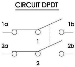
For bidirectional control of linear actuators, the industry standard is a Double Pole Double Throw (DPDT) ON-OFF-ON switch. This switch configuration provides exactly what you need: the ability to extend the actuator, stop it in position, and retract it—all from a single control point.
The terminology of poles and throws is essential to understanding switch operation. The number of poles refers to the number of separate circuits the switch can control simultaneously. A double pole switch controls two independent circuits, which is exactly what's needed to reverse polarity to a DC motor or actuator. The number of throws indicates how many positions each pole can connect to. A double throw configuration provides two distinct "ON" positions for each pole.
The "ON-OFF-ON" designation describes the switch's three positions: one ON position for extension, a center OFF position where the actuator stops and holds its position, and a second ON position for retraction. This center-off position is critical for most applications, as it allows you to stop the actuator at any point along its stroke length without maintaining constant pressure on the switch.
You may encounter DPDT ON-ON switches without a center-off position. While these can theoretically control an actuator, they lack a neutral stopping position, meaning the actuator would always be moving in one direction or the other. This configuration is rarely suitable for actuator control and should generally be avoided unless your specific application requires continuous motion in one direction or the other.
Momentary vs. Maintained Switch Operation
Beyond the basic DPDT configuration, switches are further categorized by their action type: momentary or maintained (also called sustaining or latching).
Momentary switches automatically return to their center position when released. This means the user must hold the switch in the forward or backward position for the actuator to continue moving. When released, the switch springs back to center, stopping the actuator. This design provides an inherent safety feature—if the operator releases the switch for any reason, motion immediately stops. Momentary switches are ideal for applications requiring precise positioning, where the operator wants fine control over the actuator's position, or in safety-critical applications where automatic stopping is desirable.
Maintained switches lock into whatever position they're switched to, remaining there until manually moved to another position. Toggle a maintained switch forward, and it stays forward—the actuator continues extending until it reaches its internal limit or you manually switch it to center or reverse. This configuration works well for applications where you want to set the actuator in motion and have it complete its full stroke without holding the switch, such as opening or closing a vent, deploying a panel, or extending a mechanism to its full travel.
Your choice between momentary and maintained operation depends entirely on your application requirements. Consider whether you need hands-free operation (maintained), safety-critical stopping (momentary), or precise positioning control (momentary). Both types function perfectly well for actuator control—the decision is about user experience and application demands.
Switch Styles and Features
Once you've determined the electrical configuration you need, you can explore the various physical styles and features available in DPDT switches.
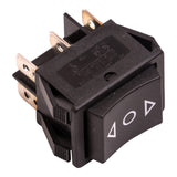
Rocker switches feature a large, rectangular actuator that rocks back and forth on a central pivot. They're popular for their ease of use and clear visual indication of position. Rocker switches are commonly found in automotive applications, marine environments, and home automation projects where a clean, modern aesthetic is desired.
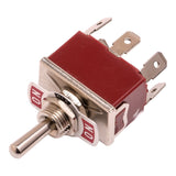
Toggle switches use a lever that flips between positions, providing positive tactile feedback with an audible click. They're extremely reliable, often rated for hundreds of thousands of operations, and their protruding lever makes them easy to operate even with gloves or in low-visibility conditions. Toggle switches are the traditional choice for industrial applications and DIY projects where durability trumps aesthetics.
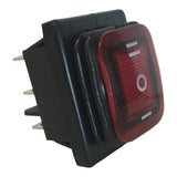
LED-illuminated switches incorporate lighting elements that can serve multiple purposes: indicating power status, showing which direction the actuator is moving, or simply improving visibility in dark environments. These switches are particularly useful in automotive applications, marine settings, or any installation where you need to locate or operate the control in low-light conditions.
Additional features to consider include environmental protection (waterproof or dust-proof ratings), panel mounting options, wire connection types (screw terminals vs. quick-connect tabs), and physical size constraints based on your installation space.
Critical Switch Specifications and Power Ratings
Understanding Power Ratings
The most critical specification when selecting a switch for actuator control is its power rating. This rating, typically expressed as maximum amperage at a specific voltage (e.g., 16A at 250V AC or 10A at 125V DC), represents the absolute limit of electrical load the switch can safely handle. Exceed this rating, and you risk welding the contacts together, burning out the switch, or creating a fire hazard.
Power ratings are not as straightforward as they might appear. A switch rated for AC current will have a significantly reduced capacity when used with DC current—often as low as 10% of its AC rating, though this isn't a hard rule. This dramatic derating occurs because DC doesn't have the natural zero-crossing point that AC provides twice per cycle. In AC circuits, the current momentarily drops to zero 120 times per second (in 60Hz systems), allowing any arc between switch contacts to naturally extinguish. DC maintains constant current flow, making arcs much harder to extinguish and causing significantly more contact wear.
Inductive Load Considerations
Linear actuators present an additional challenge: they're inductive loads. The electric motor inside an actuator contains wire coils that resist changes in current flow. When you first close a switch to power an actuator, there's an inrush of current that can be significantly higher than the steady-state running current. When you open the switch to stop the actuator, the collapsing magnetic field in the motor coils generates a voltage spike that can be many times higher than the supply voltage.
These transient overcurrent and overvoltage conditions stress switch contacts far beyond what resistive loads (like light bulbs or heaters) would cause. Even if your actuator's steady-state current draw is well within the switch's rating, the inrush and voltage spike can cause arcing that gradually erodes the contacts. Over time, this erosion increases contact resistance, generates heat, and eventually leads to switch failure.
The practical implication is clear: always select a switch with a power rating significantly higher than your actuator's requirements. A good rule of thumb is to choose a switch rated for at least 150-200% of your actuator's maximum current draw. If you're controlling multiple actuators in parallel, sum their current draws and apply the same safety margin. For a typical 12V actuator drawing 5A at maximum load, look for a switch rated for at least 8-10A DC.
Other Important Specifications
Beyond power ratings, consider these specifications when selecting your switch:
- Voltage rating: Ensure the switch is rated for your system voltage (typically 12V or 24V for actuator applications). Higher voltage ratings are acceptable, but using a switch below your system voltage is dangerous.
- Physical size: Verify the switch will fit in your intended mounting location, and that you have adequate clearance behind the panel for terminals and wiring.
- Terminal type: Screw terminals provide secure connections and are easy to service, while quick-connect terminals allow for faster assembly.
- Environmental rating: If your application involves moisture, dust, or outdoor installation, look for switches with appropriate IP (Ingress Protection) ratings.
- Life expectancy: Expressed as number of operations, this indicates how many switching cycles the device can handle before failure becomes likely. For frequently-used applications, higher-rated switches justify their additional cost.
Basic Wiring Configurations for Switch Control
Understanding DPDT Switch Terminals
A DPDT switch has six terminals arranged in two rows of three. Understanding how these terminals connect internally as the switch moves between positions is key to proper wiring. When looking at the back of the switch, you'll typically see the terminals arranged as follows:
- Top row (3 terminals): Left position contact, center common, right position contact
- Bottom row (3 terminals): Left position contact, center common, right position contact
When the switch is in its center (OFF) position, all contacts are open—nothing is connected to anything. When moved to one side, the center terminals connect to the terminals on that side. When moved to the opposite side, the center terminals connect to the terminals on that side instead.
This internal switching action is what allows the DPDT switch to reverse polarity to the actuator. By cleverly arranging which wires connect to which terminals, moving the switch physically swaps the positive and negative connections to the actuator, reversing its direction.
Configuration One: Power Supply in Middle Position
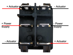
In this configuration, the power supply connects to the two center (common) terminals, with positive to one center terminal and negative to the other. The actuator connects to the outside terminals, with its positive lead connecting to both terminals on one side (one top, one bottom), and its negative lead connecting to both terminals on the opposite side (the remaining top and bottom terminals).
When the switch is moved forward, let's say the positive from the power supply connects through to the top-right terminal, and the negative connects to the bottom-right terminal. This sends current through the actuator in one direction, causing extension. When the switch is moved backward, the connections reverse—positive now connects to the bottom-left terminal and negative to the top-left terminal. Since the actuator leads are crossed on the other side of the switch, this reverses polarity to the actuator, causing retraction.
This configuration is intuitive for many people because the power supply remains in the "middle" conceptually, and the switch action directly controls which way current flows through the actuator.
Configuration Two: Actuator in Middle Position
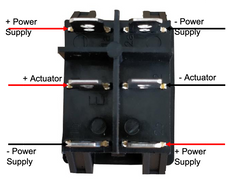
This configuration reverses the arrangement: the actuator connects to the two center (common) terminals, while the power supply connections go to the outside terminals. The power supply positive connects to both terminals on one side, and negative connects to both terminals on the opposite side.
Functionally, this achieves the same result through different means. When the switch moves to one side, the actuator's center terminals connect to one set of power supply wires, creating current flow in one direction. When the switch moves to the other side, the connections flip to the opposite set of power wires, reversing polarity and direction.
The choice between these two configurations is largely a matter of personal preference or what makes more sense for your specific installation. Consider factors like where your power supply is located relative to the switch, whether you want the actuator permanently wired to the switch or easily disconnectable, and which configuration makes troubleshooting easier in your particular setup.
Controlling Multiple Actuators with One Switch
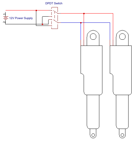
You can control multiple linear actuators simultaneously by wiring them in parallel—connecting all positive leads together and all negative leads together, then treating this parallel group as a single actuator in either of the wiring configurations described above.
This approach is excellent for synchronized motion applications, such as opening multiple panels simultaneously, lifting a load with actuators on each side, or creating symmetrical movement in furniture or automation projects. All actuators will extend and retract together, maintaining synchronized motion as long as they have similar specifications and load conditions.
However, parallel wiring comes with a critical caveat: current draw multiplies with each additional actuator. If one actuator draws 3A at maximum load, two actuators will draw 6A, three will draw 9A, and so on. This additive current draw can quickly exceed your switch's power rating. Before adding actuators in parallel, calculate the total current draw and verify your switch can handle it with appropriate safety margin. If not, you'll need to either use a higher-rated switch or implement relay-based control (discussed in the next section).
Also consider that your power supply must be rated for the combined current draw of all actuators plus a safety margin. A power supply that's adequate for one actuator may be undersized for multiple actuators operating simultaneously.
Using Relays to Overcome Power Limitations
Why Relays Matter for Actuator Control
When your actuator's current requirements exceed available switch ratings—or when controlling multiple actuators pushes total current beyond safe limits—relays provide the solution. A relay is an electromagnetically operated switch that allows a small current to control a much larger current through complete electrical isolation.
The relay's brilliance lies in its separation of control and power circuits. The switch you manually operate handles only the small current needed to energize the relay's electromagnetic coil (typically 50-200mA). This energized coil creates a magnetic field that physically moves contacts in a completely separate circuit—the high-power circuit that actually drives your actuator. Since the two circuits share no electrical connection, you can safely use a small, inexpensive switch rated for 1A to control an actuator drawing 20A or more.
Relays also help mitigate the inductive load challenges discussed earlier. Quality relays designed for motor or inductive load control incorporate contact materials and designs that better handle the arcing and voltage spikes inherent to these applications. By moving these stresses from your user-operated switch to a purpose-built relay, you dramatically improve system reliability.
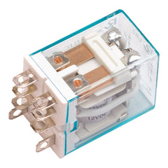
Understanding Relay Terminology
Relays use similar terminology to switches, with some additions specific to their operation:
- Coil: The electromagnetic component that, when energized, creates the magnetic field to operate the relay's contacts.
- Normally Open (NO): A contact connection that is open (disconnected) when the coil is not energized, and closes when the coil is energized.
- Normally Closed (NC): A contact connection that is closed (connected) when the coil is not energized, and opens when the coil is energized.
- Common (COM): The shared terminal that connects to either NO or NC depending on coil state.
- Poles and Throws: Same as switches—number of separate circuits and number of positions per circuit.
Just like switches, relays have power ratings for their contacts. When selecting relays for actuator control, ensure they're rated for DC inductive loads and provide adequate safety margin above your actuator's requirements. The coil voltage must match your control voltage (typically 12V or 24V), but the contact rating is independent and can handle much higher currents.
Single DPDT Relay Configuration
The simplest relay-based actuator control uses a single DPDT relay controlled by a Single Pole Single Throw (SPST) switch. In this configuration, the switch simply turns the relay coil on or off. The relay contacts are wired to reverse polarity to the actuator based on whether the coil is energized or not.
When the coil is not energized, the relay's Normally Closed contacts connect the power supply to the actuator in one polarity, causing the actuator to move in one direction (typically retraction). When you close the switch, energizing the coil, the relay contacts flip to the Normally Open position, reversing polarity and causing the actuator to extend.
The significant limitation of this configuration is the lack of an OFF position. The actuator is always moving in one direction or the other—there's no way to stop it in a mid-stroke position. This makes the single DPDT relay configuration unsuitable for most applications, though it could work for simple automated systems that only need to know "fully extended" or "fully retracted" positions.
Dual SPDT Relay Configuration with DPDT Switch
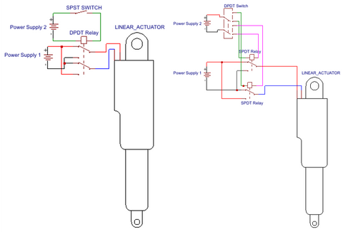
For full directional control with a center-off position, you need two Single Pole Double Throw (SPDT) relays controlled by a DPDT ON-OFF-ON switch. This configuration provides the same three-position control as a direct switch connection, but with the current-handling advantages of relays.
The two relays are wired to control polarity to the actuator. The DPDT switch controls which relay (if any) is energized. When the switch is in the center position, neither relay coil is energized, and the wiring ensures both actuator leads connect to ground (or both to positive)—either way, no voltage difference exists across the actuator, so it remains stationary.
When you move the switch forward, it energizes only the first relay. This relay's contacts close, connecting the power supply to the actuator in one polarity, causing extension. When you move the switch backward, it energizes only the second relay, which connects power in the opposite polarity, causing retraction. The switch's center-off position de-energizes both relays, stopping all motion.
This configuration requires careful wiring to ensure the de-energized state truly disconnects power from the actuator. A common approach is to wire both relays' Normally Closed contacts to ground, so when neither coil is energized, both actuator leads connect to ground. The Normally Open contacts then connect to positive and negative supply rails respectively, so energizing one relay or the other creates the voltage difference needed for motion.
Modern relay modules designed for Arduino and automation projects often include multiple SPDT relays on a single board, making this configuration easier to implement. These modules handle the coil driving circuitry and provide convenient screw terminals for power and load connections.
Limitations of Switch-Based Control
While switch-based control offers simplicity and reliability, it has inherent limitations that may make alternative control methods more suitable for certain applications.
No Independent Actuator Control
When controlling multiple linear actuators with a single switch, they all move together. You cannot selectively extend one actuator while retracting another, or move actuators in a sequence. Each actuator requires its own dedicated switch for independent control. For complex automation requiring coordinated but independent motion—such as a TV lift that also swivels, or a multi-actuator positioning system—you'll need either multiple switches or a programmable control box.
Fixed Speed Operation
Switch control provides no means to adjust actuator speed. The actuator operates at whatever speed results from applying full system voltage to it. Some applications benefit from variable speed—slower movement for precise positioning, faster movement when precision isn't critical, or reduced speed to lower noise or mechanical stress. Achieving variable speed requires PWM (Pulse Width Modulation) control or variable voltage, which demands electronic control systems beyond simple switches.
No Position Feedback Utilization
Feedback actuators incorporate potentiometers, hall-effect sensors, or optical encoders that provide real-time position information. This feedback enables precise positioning, position memory, and synchronized motion of multiple actuators even under unequal loading. However, utilizing this feedback requires a control system that can read the sensor signals and make intelligent decisions—capabilities that simple switches lack. With switch control, feedback sensors remain unused, and you rely on mechanical limit switches in the actuator to prevent over-extension or over-retraction.
When Switch Control Is Ideal
Despite these limitations, switch-based control remains the optimal choice for many applications:
- Simple automation: Opening vents, extending panels, raising TV lifts, or adjusting furniture where you only need "up" and "down"
- Manual positioning: Applications where a human operator provides the intelligence, watching the motion and stopping at the desired position
- Reliable operation: Environments where simple, proven technology trumps features—marine, agricultural, or industrial settings where serviceability matters
- Cost sensitivity: Projects where minimizing component cost and complexity is paramount
- One-off builds: Custom projects or prototypes where programming a microcontroller isn't justified
For applications requiring speed control, position memory, sequencing, or utilization of feedback sensors, consider upgrading to electronic control systems, control boxes with built-in logic, or microcontroller-based solutions using Arduino or similar platforms.
Practical Installation Tips and Best Practices
Wire Sizing and Connections
Proper wire sizing is critical for reliable operation and safety. Undersized wires create voltage drop that robs your actuator of power, and they heat up under load, creating a fire hazard. For typical 12V actuator applications, use 18 AWG wire for actuators drawing up to 3A, 16 AWG for 3-5A, and 14 AWG for 5-10A. Longer wire runs require larger gauges to compensate for resistance over distance.
Make secure, low-resistance connections at every junction. For screw terminals, ensure wires are fully inserted and screws are tight. For quick-connect terminals, verify connectors are fully seated and crimped with proper tools. Solder connections where appropriate, and use heat shrink tubing to insulate and protect connections from environmental damage.
Circuit Protection
Always include a fuse or circuit breaker in series with your power supply. Size the fuse slightly above your actuator's maximum current draw—for a 5A actuator, a 7-8A fuse provides protection without nuisance tripping. The fuse protects against short circuits and prevents runaway fault conditions from causing fires or damaging equipment.
Consider adding flyback diodes across inductive loads to suppress voltage spikes. While this adds complexity, it significantly extends switch and relay life in electrically noisy environments or with particularly large actuators.
Environmental Considerations
Mount switches in locations protected from direct moisture exposure, excessive heat, and mechanical damage. Even "waterproof" switches have limits—they resist splash and spray but may not survive submersion. If your application involves outdoor installation or moisture exposure, use switches with appropriate IP ratings and apply dielectric grease to connections.
For automotive or marine applications, consider vibration resistance. Secure all connections with lock washers or threadlocker, and provide strain relief for wires to prevent work-hardening and breakage from constant movement.
Summary and Conclusion
Controlling a linear actuator with a switch provides a straightforward, reliable solution for a wide range of automation applications. The key to success lies in proper switch selection—choosing a DPDT ON-OFF-ON configuration with adequate power rating for your actuator's demands, considering whether momentary or maintained action suits your application, and selecting a physical style that fits your installation requirements.
For standard applications with current draws within typical switch ratings (under 10A), direct switch control using either the power-in-middle or actuator-in-middle wiring configuration provides simple, effective operation. When requirements exceed switch capabilities—multiple actuators in parallel, high-force industrial actuators, or reliability concerns with inductive loads—relay-based control offers the solution while maintaining the simplicity of manual switch operation.
While switch-based control has limitations in speed adjustment, position feedback utilization, and independent multi-actuator sequencing, it remains the optimal choice for countless applications where simplicity, reliability, and direct manual control are paramount. From DIY home automation to professional installations, understanding these principles enables you to design and implement robust actuator control systems that provide years of reliable service.
Frequently Asked Questions
What type of switch do I need to control a linear actuator?
You need a Double Pole Double Throw (DPDT) ON-OFF-ON switch to properly control a linear actuator. The double pole configuration allows you to reverse polarity to the actuator, which changes its direction, while the double throw provides two ON positions (one for extension, one for retraction) plus a center OFF position where the actuator stops. This can be either a momentary switch that returns to center when released, or a maintained switch that locks in position. The choice depends on whether you want the actuator to stop automatically when you release the switch (momentary) or continue moving until you manually switch it off (maintained).
How do I wire a DPDT switch to my linear actuator?
There are two functionally equivalent wiring configurations. In the first, connect your power supply's positive and negative leads to the two center (common) terminals of the switch. Then connect your actuator's positive lead to both terminals on one outer side (top and bottom), and the actuator's negative lead to both


