Achieving precise synchronous motion between multiple linear actuators is critical for many automation projects—from trapdoor mechanisms and bi-fold doors to medical beds and industrial platforms. When two or more actuators must move in perfect unison, even slight timing differences can cause mechanical binding, uneven load distribution, or premature wear. While dedicated hardware solutions like FIRGELLI's FA-SYNC-2 and FA-SYNC-4 control boxes provide plug-and-play synchronization, engineers and DIY enthusiasts often prefer the flexibility and customization that microcontroller-based solutions offer.
This comprehensive tutorial demonstrates how to implement synchronous control of two optical linear actuators using an Arduino microcontroller and custom firmware. We'll cover the fundamental principles of encoder-based position feedback, proportional speed control algorithms, and the practical wiring and programming required to achieve smooth, synchronized motion. Whether you're building a custom automation system or seeking to understand the principles behind synchronous control, this guide provides the technical foundation you need.
This is an advanced tutorial that assumes working knowledge of Arduino hardware and software, including familiarity with pulse width modulation (PWM) signals, interrupt service routines (ISR), sensor debouncing techniques, and motor encoder operation. The implementation presented here uses a basic proportional controller as a foundation—experienced developers can extend this to full PID control loops or scale to multiple actuators as project requirements demand.
Understanding Synchronous Control Principles
Synchronous control maintains equal extension lengths between two or more linear actuators by continuously comparing their positions and dynamically adjusting motor speeds. The fundamental concept is straightforward: if one actuator begins extending faster than its counterpart, the control system reduces its speed proportionally until both actuators return to matched positions. This real-time adjustment compensates for manufacturing tolerances, uneven mechanical loads, voltage variations, and other factors that can cause actuators to drift out of sync.
The key to effective synchronous control is accurate position feedback. FIRGELLI's Optical Series actuators incorporate built-in optical encoders that provide precise position data without requiring external sensors. This encoder system consists of a perforated disc attached to the motor shaft, an infrared LED emitter, and an infrared photodetector. As the motor rotates, the disc alternately blocks and transmits the infrared beam, generating a square wave signal where each pulse corresponds to a specific increment of travel.
Position tracking accuracy varies by actuator model: the 35-pound capacity optical actuator generates approximately 50 pulses per inch of travel (with a tolerance of ±5 pulses per inch), while the 200-pound and 400-pound models produce approximately 100 pulses per inch (±5 pulses per inch). These pulse counts allow the Arduino to calculate both the instantaneous speed and absolute position of each actuator with sub-millimeter precision when properly calibrated.
Required Components and Specifications
To implement this synchronous control system, you'll need the following components:
- Two Optical Series Linear Actuators: Available in 35lb, 200lb, or 400lb force ratings with integrated optical encoders. Ensure both actuators have identical stroke lengths for optimal synchronization.
- Two IBT-2 Motor Driver Modules: These high-current H-bridge drivers can handle up to 43A peak current and support PWM speed control. Each actuator requires its own dedicated driver for independent speed regulation.
- Arduino Uno (or compatible): Provides the processing power and interrupt capability needed for real-time encoder monitoring and control algorithm execution.
- 12V DC Power Supply: Must provide sufficient current for both actuators operating simultaneously under load. Calculate minimum required current based on actuator specifications and expected duty cycle.
- Three Momentary Push Buttons: For manual extend, retract, and stop commands during testing and operation.
- Hookup Wire: Use appropriately gauged wire for power connections (14-16 AWG recommended for motor power) and 22-24 AWG for signal connections.
Wiring Diagram and Connections
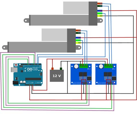
Follow the wiring diagram carefully, paying particular attention to the following critical connections:
Encoder Signal Connections: The optical encoder outputs from each actuator must connect to Arduino interrupt-capable pins. For the Arduino Uno, digital pins 2 and 3 are the only pins with hardware interrupt capability, making them ideal for encoder pulse counting. These connections are time-critical and cannot be reliably implemented using polling methods.
Motor Driver Connections: Each IBT-2 driver requires PWM inputs for direction and speed control. The RPWM (forward) and LPWM (reverse) pins accept PWM signals from the Arduino, while the R_EN and L_EN enable pins should be connected to 5V to activate the driver. The motor power outputs connect directly to the actuator's red (positive) and black (negative) motor wires.
Power Distribution: The 12V power supply connects to the VCC and GND terminals on both IBT-2 drivers. Ensure your power supply can deliver adequate current—simultaneous operation of two 200lb actuators under full load may require 10A or more. Use separate ground connections for motor power and logic signals to minimize electrical noise.
Control Button Wiring: Connect the three momentary buttons between digital pins 7, 8, 9 and GND. The Arduino's internal pull-up resistors will be enabled in software, eliminating the need for external resistors. These buttons provide extend, retract, and emergency stop functionality.
Important: Always verify the wire color coding on your specific actuators before making connections, as manufacturing batches may use different color conventions than shown in the diagram. Incorrect connections can damage the encoder circuitry or motor drivers.
Quick Start Implementation Guide
For those wanting to achieve synchronous motion quickly, follow this streamlined implementation process:
- Make Physical Connections: Wire all components exactly as shown in the diagram above. Double-check all power connections and encoder signal routing before applying power.
- Upload Calibration Program: Load the calibration sketch (provided below) onto your Arduino. This program measures the precise pulse count for your specific actuators over a complete extension and retraction cycle.
- Record Calibration Values: Run the calibration program and note the two output values displayed in the Serial Monitor. These numbers represent the total pulse count for each actuator and compensate for manufacturing tolerances.
- Configure Synchronous Program: Copy the recorded calibration values into line 23 of the synchronous control program, replacing the placeholder array {908, 906} with your measured values.
- Adjust Timing for 35lb Actuators: If using 35-pound capacity actuators, change the falsepulseDelay variable on line 29 from 20 milliseconds to 8 milliseconds to accommodate their higher encoder pulse frequency.
- Upload and Test: Load the synchronous control program and test basic operation using the control buttons. Monitor the Serial output to verify both actuators maintain synchronized positions.
- Fine-Tune Performance: Adjust the K_p proportional gain variable (line 37) to optimize response time and minimize oscillation. Start with the default value and increase or decrease based on observed behavior under your specific load conditions.
For advanced tuning, connect a potentiometer to analog pin A0 and add code to read the potentiometer value, allowing real-time adjustment of the K_p gain: K_p = map(analogRead(A0), 0, 1023, 0, 20000);
Calibration Program Overview
Accurate calibration is essential for reliable synchronous operation. Due to manufacturing tolerances in the encoder disc perforation spacing and mechanical drivetrain components, the actual pulse count per inch varies slightly between individual actuators—even those from the same production batch. The calibration program measures the exact pulse count for each actuator, eliminating these variations from the control algorithm.
The calibration process works as follows:
Initial Retraction: The program begins by fully retracting both actuators (line 53), establishing a known reference position. During this initial retraction, the pulse counters are reset to zero, providing a clean starting point for measurement.
Full Extension Cycle: After reaching the fully retracted position, both actuators extend completely while the interrupt service routine counts every encoder pulse (line 153 and 166). This forward motion provides the first data point for calibration.
Return Retraction Cycle: The actuators then retract fully again (line 74), with pulse counting continuing throughout the motion. This reverse motion completes the measurement cycle.
Averaging and Output: The program averages the pulse counts from the extension and retraction cycles, compensating for any directional variations in the encoder or mechanical backlash. The final averaged values are output via Serial communication (line 88) for recording and use in the synchronous control program.
This two-way measurement approach provides more accurate calibration than single-direction measurement, as it accounts for mechanical hysteresis and encoder irregularities that may affect forward versus reverse motion differently.
Calibration Code
Synchronous Control Program Overview
The synchronous control program implements a real-time proportional controller that continuously compares actuator positions and adjusts speeds to maintain synchronized motion. This represents a practical implementation of closed-loop control theory applied to multi-actuator systems.
Position Error Calculation: At the core of the control algorithm is continuous position comparison. The program reads the encoder pulse count from each actuator and calculates the position difference. This error value represents how far out of synchronization the actuators have drifted.
Proportional Speed Adjustment: The calculated position error multiplies by the proportional gain constant K_p (line 37), generating a speed correction value. If one actuator has extended further than the other, the control system reduces its speed proportionally while maintaining or increasing the speed of the trailing actuator. The magnitude of speed adjustment scales with the position error—larger synchronization errors produce larger speed corrections.
PWM Output Generation: The corrected speed values convert to PWM duty cycles that drive the IBT-2 motor controllers. Higher PWM duty cycles produce faster motor rotation, while lower values reduce speed. The proportional controller continuously modulates these PWM signals to maintain position synchronization.
Direction Control: The three control buttons (extend, retract, stop) provide user commands that the program interprets and executes on both actuators simultaneously. During normal operation, the synchronization algorithm runs continuously, ensuring both actuators maintain matched positions regardless of load variations or other disturbances.
Interrupt-Driven Counting: Position measurement occurs through interrupt service routines triggered by each encoder pulse. This interrupt-driven approach ensures no pulses are missed, even during intensive computation periods. The ISR functions increment position counters with microsecond precision, providing the accurate feedback necessary for tight synchronization.
Performance Considerations
The example implementation uses a simple proportional controller, which offers several advantages: straightforward tuning, predictable behavior, and computational efficiency. However, proportional-only control exhibits inherent limitations including steady-state error under load and potential oscillation around the target position. The system may experience overshoot when correcting large position errors, particularly with aggressive K_p values.
For applications requiring tighter synchronization tolerances or operation under highly variable loads, implementing a full PID (Proportional-Integral-Derivative) control loop provides superior performance. The integral term eliminates steady-state error, while the derivative term reduces overshoot and improves damping. PID implementation is beyond the scope of this introductory tutorial but represents a logical next step for advanced users.
Synchronous Control Code
Using Bullet Actuators for Synchronous Control
In addition to the Optical Series, FIRGELLI offers bullet actuators with integrated Hall Effect encoders: the Bullet 36 Cal. and Bullet 50 Cal. models. These high-performance actuators use magnetic sensing rather than optical detection, offering enhanced reliability in dusty or dirty environments where optical encoders may be compromised.
Hall Effect encoders differ from optical encoders in several important ways. Rather than detecting light interruption, Hall Effect sensors respond to changes in magnetic field strength as a magnetized disc rotates past the sensor. This magnetic sensing remains unaffected by ambient light, dust, oil, or other environmental contaminants that can interfere with optical systems.
More significantly, the Bullet Series actuators incorporate quadrature encoders, which generate two pulse trains phase-shifted by 90 degrees. This quadrature output provides two critical advantages: directional sensing (determining whether the actuator extends or retracts based on the phase relationship) and doubled resolution (counting both rising and falling edges on both channels effectively quadruples the pulse count compared to single-channel encoding).
Arduino Requirements for Quadrature Encoding
Implementing synchronous control with quadrature feedback actuators requires an Arduino board with at least four hardware interrupt pins—two interrupts per actuator to monitor both encoder channels. The Arduino Uno's limitation to two interrupt pins makes it unsuitable for this application. Consider these alternatives:
- Arduino Mega 2560: Provides six hardware interrupt pins (2, 3, 18, 19, 20, 21), sufficient for up to three quadrature-encoded actuators.
- Arduino Due: All digital pins support interrupts, offering maximum flexibility for complex multi-actuator systems.
- Teensy 3.x/4.x: Provides numerous interrupt-capable pins with faster processing speeds for demanding control applications.
The code modifications required for quadrature encoding include expanded interrupt service routines to process both encoder channels, directional logic based on phase relationships, and adjusted debounce timing. The falsepulseDelay variable requires tuning specific to Hall Effect sensor characteristics, which differ from optical encoder timing requirements.
Advanced Implementation Techniques
Scaling Beyond Two Actuators
Many applications require synchronizing three, four, or more linear actuators—consider large bi-fold doors, multi-segment platforms, or adjustable workstation systems. Scaling the basic two-actuator system to multiple units requires both hardware and software considerations.
From a hardware perspective, select an Arduino board with sufficient interrupt pins for your actuator count. Each optical encoder requires one interrupt pin, while each quadrature encoder needs two. The Arduino Mega 2560's six interrupt pins limit you to six optical encoders or three quadrature encoders maximum.
Software scalability benefits greatly from array-based vectorized programming. Rather than duplicating code blocks for each actuator, store actuator parameters (pin assignments, pulse counts, current positions, target speeds) in arrays and use for() loops to iterate through all actuators. This approach reduces code size, simplifies maintenance, and makes adding additional actuators trivial—simply increase array dimensions and update loop boundaries.
Signal Debouncing Techniques
Encoder signals, like mechanical switch contacts, suffer from electrical noise and mechanical vibration that can generate false pulses. Without proper debouncing, a single physical encoder transition may register as multiple pulses, corrupting position data and degrading synchronization accuracy.
The example code implements time-based software debouncing using the falsepulseDelay variable. After detecting an encoder transition, the ISR ignores subsequent transitions for a defined period (8-20 milliseconds depending on actuator model). This approach works well for most applications but consumes processor time and may miss legitimate high-speed pulses under certain conditions.
For more robust operation, consider hardware debouncing using RC filter circuits on encoder signal lines or Schmitt trigger inputs. These solutions eliminate noise at the hardware level before signals reach the Arduino, improving reliability without consuming processing resources. A simple 100Ω resistor and 0.1µF capacitor forms an effective low-pass filter for most encoder signals.
Handling millis() Rollover
The Arduino millis() function returns an unsigned long value representing milliseconds since program start. This 32-bit value rolls over (resets to zero) after approximately 49.7 days of continuous operation. Any timing code that compares millis() values without accounting for rollover will fail catastrophically when rollover occurs.
The provided interrupt service routines include rollover-safe timing comparisons. The critical technique involves calculating elapsed time using subtraction: elapsedTime = currentTime - previousTime. In unsigned arithmetic, this subtraction produces the correct elapsed time even when currentTime has rolled over and is numerically smaller than previousTime.
For example, if previousTime equals 4,294,967,290 (5 milliseconds before rollover) and currentTime equals 10 (10 milliseconds after rollover), the subtraction 10 - 4,294,967,290 produces 16 when evaluated as unsigned long arithmetic—correctly representing 16 milliseconds elapsed time despite the rollover event.
Any modifications to the timing code must preserve this rollover-safe subtraction method. Direct comparisons like if (currentTime > previousTime + timeout) will fail at rollover. Instead, use if ((currentTime - previousTime) > timeout) to maintain rollover safety.
Troubleshooting Common Issues
Actuators Move at Different Speeds: Verify calibration values are correctly entered in the synchronous control program. Re-run calibration if necessary. Check that both actuators use identical models with the same specifications. Ensure power supply voltage remains stable under load—voltage drops can cause speed variations.
System Oscillates or Hunts: Reduce the K_p proportional gain value. Excessive gain causes the controller to overreact to position errors, resulting in oscillation around the target position. Start with lower K_p values and gradually increase until achieving acceptable response without oscillation.
One Actuator Doesn't Move: Verify motor driver connections and ensure enable pins are properly connected to 5V. Check actuator power connections and confirm adequate power supply current capacity. Test the encoder signal using Serial.println() statements to verify pulse detection on the affected actuator.
Position Drift Over Time: Examine encoder signal wiring for electrical noise pickup. Implement hardware debouncing or adjust falsepulseDelay values. Verify that interrupt service routines execute without delay—time-intensive code in ISRs can cause missed pulses.
Erratic Behavior Under Load: Insufficient power supply capacity causes voltage sag during high-current operation, affecting motor speed and controller behavior. Use a power supply rated for at least 150% of calculated maximum current draw. Consider implementing current limiting or duty cycle restrictions to prevent power supply overload.
Safety and Best Practices
When implementing custom control systems for linear actuators, follow these safety guidelines:
- Implement emergency stop functionality that immediately halts all actuator motion regardless of program state
- Add limit switch monitoring in software to detect mechanical end-of-travel conditions and prevent over-extension
- Include timeout mechanisms that stop actuators if they fail to reach target positions within expected timeframes
- Test thoroughly with light loads before applying full operational loads
- Use appropriate wire gauges for current capacity—undersized wiring creates fire hazards
- Implement software safety margins that stop actuators slightly before physical travel limits
- Add status LEDs to indicate system state (idle, extending, retracting, error) for operational awareness
- Consider watchdog timer implementation to reset the system if the main program loop hangs
For applications involving human interaction or potential pinch points, incorporate additional safety measures including pressure-sensitive safety edges, redundant position sensing, or force-limiting control algorithms.
Conclusion
Arduino-based synchronous control of multiple linear actuators provides a flexible, cost-effective solution for custom automation projects while offering deeper insight into control system principles. The implementation presented here establishes a solid foundation using optical encoder feedback and proportional control. While this approach works well for many applications, it represents just the starting point for sophisticated motion control systems.
Engineers seeking production-grade synchronization with minimal development time should consider FIRGELLI's dedicated FA-SYNC-2 and FA-SYNC-4 control boxes, which provide pre-engineered solutions with guaranteed performance specifications. For those pursuing custom implementations, the techniques and code provided here offer a proven framework that can be extended with PID control, multi-actuator arrays, or integration with larger automation systems.
Remember that FIRGELLI Automations provides these tutorials as educational resources for the DIY and maker communities. While we cannot offer technical support for custom Arduino implementations, the engineering principles and example code presented here have been tested and validated for the specified hardware configurations.
Frequently Asked Questions
Can I use Arduino synchronization with non-optical actuators?
Standard linear actuators without built-in encoders cannot be synchronized using this method, as there's no position feedback available. However, you have several alternatives: upgrade to feedback actuators with integrated encoders (optical or Hall Effect), add external rotary encoders to the actuator motor shafts, or use external position sensors such as linear potentiometers or ultrasonic distance sensors. External encoder installation requires mechanical mounting provisions and careful calibration but can work with any actuator model.
What is the maximum number of actuators I can synchronize with Arduino?
The practical limit depends on your Arduino model's interrupt pin availability and processing capacity. An Arduino Uno's two interrupt pins limit you to two optical actuators maximum. The Arduino Mega 2560's six interrupt pins support up to six optical actuators or three quadrature-encoded actuators. For larger systems with 8-16 actuators, consider using external interrupt expansion ICs or dedicated motion control boards. Keep in mind that computational load increases with actuator count—complex control algorithms may require faster processors like the Arduino Due or Teensy 4.0.
Why does my system oscillate instead of holding steady position?
Oscillation indicates excessive proportional gain (K_p value too high) causing the controller to overcorrect position errors. Reduce K_p gradually until oscillation stops—typical working values range from 1 to 20 depending on actuator specifications and load characteristics. If reducing K_p eliminates oscillation but makes response too slow, implement a full PID controller where the derivative term provides damping while maintaining responsive control. Also verify that mechanical binding or excessive friction isn't creating stick-slip behavior that appears similar to control oscillation.
Can this system handle significantly different loads on each actuator?
The proportional controller can compensate for moderate load differences (up to about 30-40% load variation) by adjusting speeds to maintain synchronization. However, extreme load imbalances may exceed the system's ability to compensate, particularly if one actuator operates at or near its force capacity while the other runs lightly loaded. For applications with predictable but different loads per actuator, implement load-specific speed curves or gain scheduling that adjusts control parameters based on operating conditions. If load imbalances approach actuator capacity limits, reconsider the mechanical design to balance loads more evenly.
How accurate is Arduino-based synchronization compared to dedicated control boxes?
Properly implemented Arduino synchronization can achieve position accuracy within 1-2% of stroke length under consistent loads, which suffices for many applications like trapdoors, hatches, or TV lifts. FIRGELLI's FA-SYNC control boxes typically maintain tighter tolerances (under 1% deviation) through optimized hardware and firmware, plus they include features like automatic end-of-travel detection and built-in safety limits. The Arduino approach offers customization flexibility and lower component cost but requires development time and testing. For critical applications requiring guaranteed specifications, certified safety compliance, or minimal development risk, dedicated control boxes provide superior reliability and support.
What happens if one encoder fails during operation?
Encoder failure typically manifests as either continuous pulse generation (shorted signal) or no pulses (open circuit). Either condition causes severe synchronization errors as the control algorithm receives invalid position data. Implement encoder health monitoring by tracking pulse frequency and flagging anomalies—encoders that suddenly stop generating pulses during motion or produce pulses while stopped indicate failures. When detected, your safety code should immediately halt all actuators and set an error flag. For mission-critical applications, consider redundant position sensing using dual encoders or supplementary sensors like limit switches at key positions to provide fault tolerance.


