This project shows you how to leverage a TiVo remote control and an Arduino board to operate a linear actuator to lift a painting that covers a TV. Watch the video at the end
Tools required
The following tools will be required to complete this project.
- #0 phillips screwdriver
- Soldering iron
- Solder
- Wire cutters
- Small pliers (I used pliers designed for working with small electronics)
Parts list
The following parts are needed to complete this project.
- Heavy Duty Track Actuator from Firgelli Automations
- TiVo Roamio remote control
- Arduino Uno Rev 3
- Hammond 1591ESBK ABS Project Box Black (7.5” x 4.3” x 2.2”)
- Microtivity IB171 170-point Mini Breadboard for Arduino
- Infrared Receiver 2.5–5.5V 38kHz
- 100PCS Michael Josh 20CM M/F Jumper Wires Cables 1 Pin Plug Male to Female
- SainSmart 2-Channel Relay Module
- USB 2.0 Cable — A-Male to B-Male
- 4 feet of 18/5 Black Sprinkler Wire
- 8 qty #4–40 x 2” stainless machine screws (I purchased them from Home Depot)
- 8 qty Everbuilt #4–40 machine screw nuts (I purchased them from Home Depot)
- 16 qty ½” nylon spacers (I purchased them from Home Depot)
- 1 qty zip tie
Setting up the Arduino Uno Rev 3
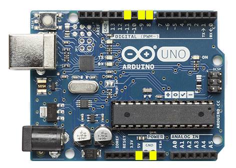
We will use the following pins on the Arduino board highlighted in yellow.
- Power 5V
- Digital #8
- Digital #9
- Digital #11
- Power GND
Setting up the SainSmart 2-channel relay module
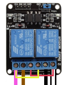
We have to jumper the SainSmart relay module in order to coincide with the Firgelli Automations linear actuator. There is a blue jumper from JD-VCC to VCC. Leave this in place as-is.
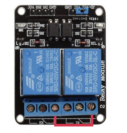
Jumper K1 position 1 to K2 position 1
Place a jumper wire from the first position on the K1 relay to the first position on the K2 relay. Our jumper is shown in red.
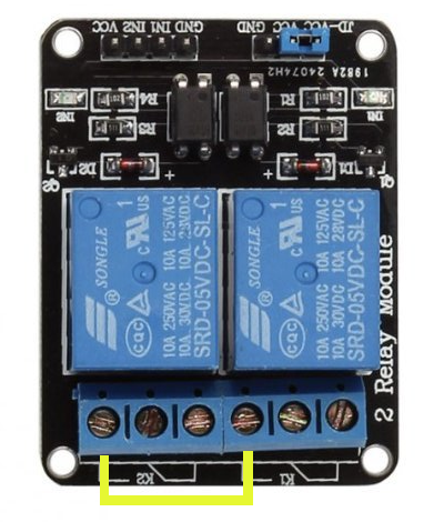
Jumper K1 position 3 to K2 position 3
Place a jumper wire from the third position on the K1 relay to the third position on the K2 relay. Our jumper is shown in yellow.
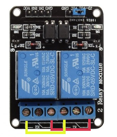
When properly jumped you should see the following configuration.
Setting up the infrared sensor
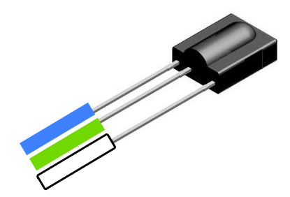
The infrared sensor has three wires that come off of it. One is for a ground wire, one is for a 5V power wire, and the third sends out the signal to our Arduino board.
Strip back two inches of the outer shield on the 18–5 sprinkler wire to expose the colored wires inside. We will only use the green, white, and blue wires so cut off the others so we don’t have to mess with them.
Strip off ⅛” of insulation on each of the wires we will use. These will be soldered to the relay using the following configuration. When looking at the sensor from the top with the round bump facing you:
- Solder the blue wire to the left terminal.
- Solder the green wire to the middle terminal.
- Solder the white wire to the right terminal.
Setting up the wiring harness of the linear actuator
The linear actuator comes with a wired remote control with two triangle buttons. One button activates a switch that moves the linear actuator up and the other moves it down.
Remove the circuit board remote control body
The first thing is to unscrew the wires in the back of the remote control. These will need to be removed with a #0 phillips screwdriver.
Remove the circuit board from the remote control body and examine the wires. Looking at it from the bottom it should have four wires soldered to the board. From left to right they are black, white, purple, and brown as shown below.
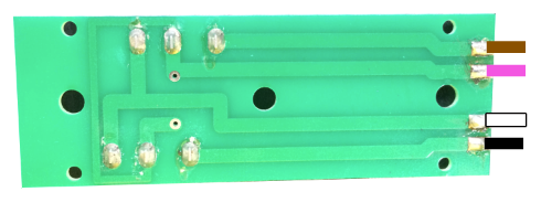
If for some reason they used different colors, simply keep track of the colors in the same order as below.
Unsolder the wires
Using a soldering iron, remove the wires from the circuit board. Gently press the tip of the soldering iron onto the existing solder on the solder point to loosen it and using a small pair of pliers gently pull the wire off the soldering point.
Attach the wires to the relays
We will now attach the wires from the wired remote control to the SainSmart 2-channel relay. Use the #0 Phillips screwdriver to unscrew the terminal and then tighten it back down to secure the wire.
- The white wire will go into K1 position 1
- The black wire will go into K1 position 2
- The brown wire will go into K2 position 2
- The purple wire will go into K2 position 3
Note: do not remove the existing jumper wires. Leave them in when you screw in the terminals.
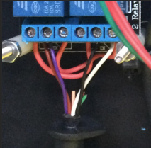
When done it should look like the above images.
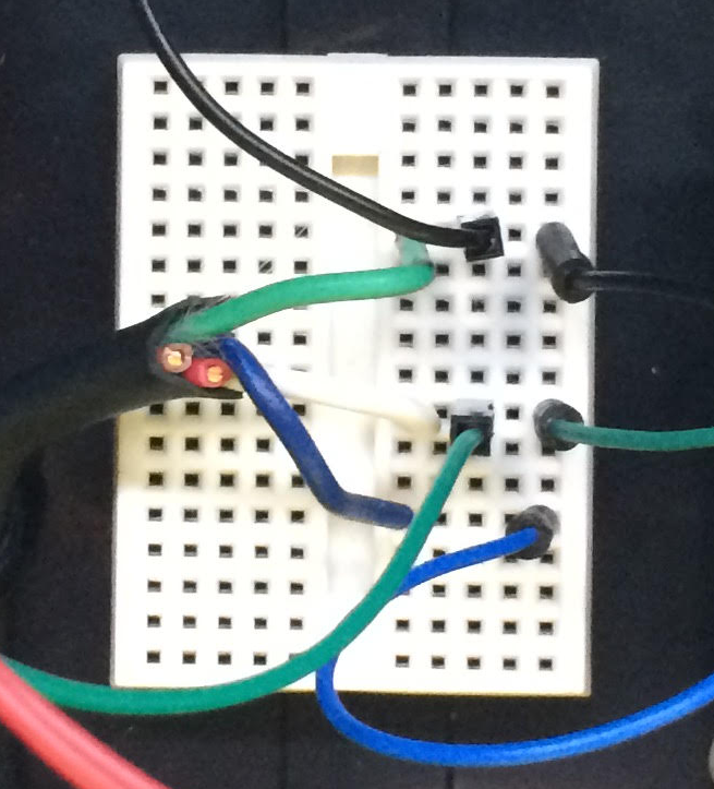
Wiring up the breadboard
We will now wire up the Arduino board to the breadboard. The breadboard allows us to jumper connections where there are multiple connections being made to one terminal on the Arduino or on the relay.
Each row of holes are connected together allowing us to jumper everything on that row. Here are the items that we will need to wire up.
5V power
- Use a male-female jumper wire from the Power 5V terminal on the Arduino to an unused row on the breadboard. Push it into a hole on the row.
- Use a male-female jumper wire from the same row on the breadboard to the VCC terminal on the SainSmart 2-channel relay. Push it into a hole on the same row.
- Expose ¼” of the white wire from the other side of the 18–5 sprinkler wire. Push it into a hole on the same row.
Ground
- Use a male-female jumper wire from the Power GND terminal on the Arduino to an unused row on the breadboard. Push it into a hole on the row.
- Use a male-female jumper wire from the GND terminal on the SainSmart 2-channel relay to a hole on the same row as the other GND wire. Push it into the hole on the same row.
- Expose ¼” of the green wire from the other side of the 18–5 sprinkler wire. Push it into a hole on the same row.
Signaling
- Use a male-female jumper wire from the Digital #11 terminal on the Arduino to an unused row on the breadboard. Push it into a hole on the row.
- Expose ¼” of the blue wire from the other side of the 18–5 sprinkler wire. Push it into a hole on the same row.
When done the breadboard should look something like the following image.
Install the the control program on the Arduino
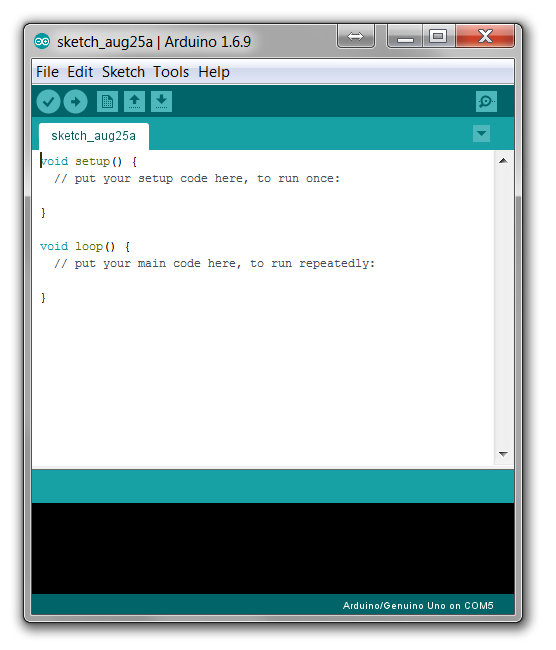
You will need to download and install the Arduino IDE. Once you have downloaded and installed the IDE, open up the IDE.
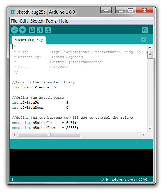
Copy and paste the code into the IDE
Download or copy the source code from GitHub and paste it into the IDE’s window which should look like this when done.
Adjust the IRremote.cpp file
There is a file in the C:\Program Files (x86)\Arduino\libraries\RobotIRremote\src\ directory that has a source code issue preventing the GitHub source code from compiling. Open the IRremoteTools.cpp file in a simple text editor like notepad and change the following line:
Line 5 should look like:
int RECV_PIN = TKD2; // the pin the IR receiver is connected to
Change it to the following and save the file.
int RECV_PIN = 11; // the pin the IR receiver is connected to
Connect the arduino to your computer using the USB cable
Place the Arduino, breadboard, and relay boards on a non-conductive surface such as a wood desk.
Connect the rectangle side of the USB cable to your computer and the “D” side to the Arduino board.
Select the port
Select the Tools — Port menu item and select the one that shows your Arduino board.
Upload the code
Select the Sketch — Upload menu item to upload the code to the Arduino.
Test the code
After the code has uploaded, plug the wire harness from the Firgelli Automations linear actuator back into the actuator and plug in the actuator.
Keep the Arduino board plugged into your computer via the USB cable.
Point your TiVo remote control at the infrared sensor and click the green thumb “like” button. The actuator should move up.
Point your TiVo remote control at the infrared sensor and click the red thumb “dislike” button. The actuator should move down.
Box it all up
I used the Hammond project box along with the machine screws, spacers, and machine screw nuts to house my circuit boards. I used a point tip on the soldering iron to poke holes through the black plastic box as well as make room for the wires through the sides. I used the zip tie to keep the wire for the infrared sensor from getting pulled out. The control wires on the Firgelli Automations linear actuator have a piece of rubber designed to prevent them from being pulled out so I was able to leverage it.
About the author
Richard Bagdonas is a data integration expert with over 15 years of experience integrating with point of sale, electronic health record, customer relationship management, and warehouse management systems. Richard has tinkered with electronics since he was a kid and this is his first Arduino project.
Richard is currently Chief Healthcare Architect at MI7 where he oversees the company’s integration with electronic health record systems.


