Actuator Mounting Bracket :
A mounting Bracket was fabricated from steel to hold the Linear Actuator.
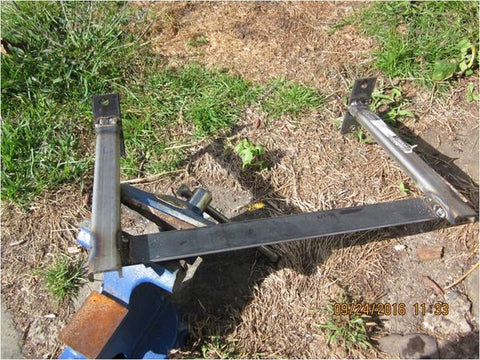
Checking The Orientation
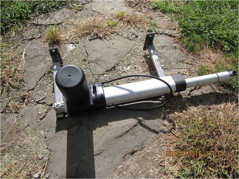
Actuator will be mounted in this manner. The bracket will attach to the transom. I selected a 9 inch actuator, 12 VDC Deluxe Model.
Bracket Mount To Transom
OutBoard Motor Attachment
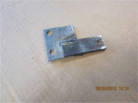
A bracket was made to allow attachment of a Quick Disconnect Link Arm to the Outboard motor. This bracket had to be reworked later. Trial and error.
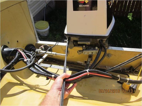
Bracket Attached To The Outboard Motor
Shows the manual steering link attached, and a quick disconnect ball (from Panther Marine) was installed. This ball will be used to attach a long rod to the kicker/Trolling Motor so that both the 70 HP Outboard and the 9.9 kicker motor will be driven by the linear actuator.
Caution, when designing the actuator mount, and the Outboard Motor Bracket, be sure to consider the Motor Tilt. I didn’t and I had to rework the brackets to allow the Outboard Motor to Tilt Properly! Trial and Error. ALSO NOTICE the manual steering attachment bolt has been REPLACED with a Hitch Pin- allows quick removal and installation. See the arrow.
Mount Firgelli Automation Actuator To The Mounting Bracket You Made.
Step 9: Actuator End Mount
Step 10: Quick Disconnect Link fabrication.
Cutting Grade 8 fine thread bolt head off. This will allow the bolt to slide inside a hollow steel tube
Step 11: Weld the bolts to the hollow tubing
Important: You have to determine what length of quick disconnect link you need to attach the Linear actuator to the outboard motor bracket. This is probably the most challenging Part. 1. I extended the motor all the way and made a mark on the piston at the halfway location, in my case the actuator drives 9 inches so the half extended distance was 4.5 inches. 2. Then I positioned the Outboard Motor in its centre of travel (straight ahead). 3. Then I measured from the actuator end hole to the ball on the mounting bracket., with the actuator set at its half extension point. 3. The distance from the actuator end hole (which will have a ball attached) to the mount bracket Ball, is the length you need for your quick disconnect rod. In my case it was 9.75 inches.
Step 12: Finished Quick Disconnect Link
I needed my Link to be 9.75 inches to allow the Linear actuator to travel to its full stops, and quit driving. The length is critical because you need the actuator to stop driving at the end of its travel (there are built in travel stop switches). If you don’t have the proper length, the motor will continue driving when it reaches the end the allowable travel, and it will wear out quicker. You need to do all these measurements before you order the actuator so you get an actuator that matches the amount of travel your outboard motor has when it swings from full left to right. Panther Marine for the Quick disconnect hardware.
Step 13: View of the Quick Disconnect Link Attachment
Notice the actuator is half extended: 4.5 inches. And in this position the Outboard Motor is straight ahead. Now when the actuator drives out and in, the motor will be moved left and right to its full travel. I found nine inches of travel was sufficient, and 12 inches would have been too much. The motor would never reach its automatic cutoff spot and would just keep driving. The mark you see on the actuator arm towards the end, is the spot marking the actuator arm when it is fully RETRACTED. You can’t see the mark I made at the centre or halfway extended position, in this picture. Trust me, this is half extended, and this is where you want the motor to be straight ahead.
Step 14: Another View
You will notice some differences in some of the pictures. For example, the small bracket I made to attach the quick links to the outboard motor. The bracket had to be re-made at least once, so everything worked without binding or hitting each other. But hopefully you get the idea. The initial way caused the long arm to hit the short quick disconnect arm, during travel, so I had to rebuild the bracket. I think this is the final arrangement. I disconnect the main steering cable (see it on the left) from the motor when using the electric steering. It creates too much friction. I just replaced the attachment bolt with a hitch pin to make it easy to connect and disconnect.
Step 15: Long Quick Disconnect Link
A longer arm was fabricated and attaches to the Kicker Motor so it will also be driven. I found I have better control when trolling, if both motors are driven- better rudder action in the wind or waves. So even when just running the kicker at low speed trolling, I also drive the big motor steering. This arrangement will allow me to remove the kicker motor link and raise the kicker motor if I just want to run the big motor off the autopilot. Also, if the electric motor steering fails, I can disconnect it, and reconnect the manual steering and manually steer.
Step 16: Joystick
I installed a Joystick to control the Linear Actuator. A toggle switch was installed in the lower right side of the panel. It can be seen below the ignition key switch. I have not labelled the switch yet. It allows you to select Manual electric steering using the Joystick, or you can select Autopilot. In autopilot position, the Linear Actuator is driven by an Arduino Based Home-Made Autopilot created by Jack Edwards. The autopilot has heading mode, and knob steering mode. You can steer the autopilot using the potentiometer knob as well as magnetic heading mode. You can see the potentiometer knob below the toggle switch. GPS steering is available, but I have not done this yet. Requires just another arduino board, $56, and of course a compatible GPS unit.
Step 17: Arduino Mega 2560 Autopilot
You can find this on YouTube- Search Jack Edwards Arduino based autopilot. I built it for heading and knob steering only. Next Summer I will add GPS steering. Not shown are the BNO 55 magnetic Heading sensor, and the Power Board that drives the actuator, a Polulo Qik PWM module. I used the exact components called out in Jack Edwards instructions. I did not use Arduino Shield interface board, I just plugged my wires directly into the arduino board itself- easy peasy. I had to change a software setting to make my system behave better. For example, it took 30 degrees of heading change before my actuator started driving. I changed one number in Jack’s program to make it so that 3 degrees of heading change makes the actuator drive. This was: motorspeed_min. At code version J11 this is at line #378. It was set at 30. Jack said set it to 127 for full motor drive with any error. I decided to set it to 75, and now my actuator drives with 3 degrees of heading error. May need to tweak this after on the water testing. There is also a deadband setting, and it is set to 2 degrees. This means nothing happens until more than 2 degrees of error occurs. This is necessary because you don't want the AP to be driving all the time with minor wave and wind action. I left this where Jack had it set.
Step 18: Autopilot Instructions
Double Click it to read instructions. The only component I used that was different than shown, was the keypad. I got one from amazon $4.95. had to change the wiring a bit to get it to work.
Step 19: Autopilot wiring diagram
You have to go to Jack Edward’s dropbox to download the software he wrote, as well as the fritzing diagram (wiring diagram) The schematic diagram was useless really, you don’t need it. just get the wiring diagram. It is a pictorial, and shows what wire to connect where. Be sure to install inline fuses. You will need a soldering iron, 60/40 rosin core solder, and soldering skills to attach the wires to the boards that connect to the arduino board (PWM, Magnetic sensor, KeyBoard, Potentiometer). On the arduino board itself, you don’t solder to it, it has connectors that you just push a pin into. So buy some of the ribbon cable that has the small pins on them. You can cut the pin off one end, and extend the wire (solder a longer wire on) as needed. As I said, I did not use the breakout board he shows in his drawing, so can eliminate it.


