Synchronizing multiple linear actuators in motion control applications presents unique engineering challenges, particularly when you need to automate the system beyond simple manual control. While the FIRGELLI Automations FA-SYNC-X series control boards provide robust synchronization capabilities out of the box, integrating them with an Arduino microcontroller unlocks significant automation potential. This combination allows you to create intelligent systems that respond to sensor inputs, follow programmed sequences, and execute complex motion profiles—all while maintaining the critical synchronization that prevents mechanical stress and premature failure.
In applications ranging from automated solar tracking systems to RV roof lifts and custom industrial machinery, the ability to control synchronized actuators programmatically transforms simple mechanical systems into sophisticated automation solutions. This tutorial provides a comprehensive guide to integrating the FA-SYNC-2 and FA-SYNC-4 boards with Arduino microcontrollers, covering everything from initial setup and wiring to code implementation and troubleshooting common challenges.
Whether you're an experienced automation engineer or a DIY enthusiast tackling your first multi-actuator project, understanding how to leverage both the FA-SYNC-X's hardware-level synchronization and Arduino's programming flexibility will significantly expand your design capabilities.
Understanding the FA-SYNC-X Synchronous Control Technology
The FIRGELLI Automations FA-SYNC-2 and FA-SYNC-4 synchronous control boards represent specialized hardware solutions designed to solve a fundamental problem in multi-actuator systems: maintaining synchronized movement under varying loads. When multiple linear actuators work together to move a single load, even slight differences in speed or position can create dangerous mechanical stress, leading to binding, bent components, or catastrophic failure.

How Hardware Synchronization Works
The FA-SYNC-X boards achieve synchronization by continuously monitoring the position feedback from each connected actuator and dynamically adjusting motor power to slower units. This closed-loop control system operates at the hardware level, processing feedback signals in real-time without software latency. When one actuator encounters increased resistance or load, the controller automatically compensates by slowing faster actuators to match, ensuring all units remain within tight positional tolerances throughout the entire stroke.
This approach differs fundamentally from software-only solutions that attempt to match actuator speeds through programming alone. Hardware synchronization responds instantaneously to load variations, mechanical friction changes, and voltage fluctuations—factors that would cause positional drift in purely software-controlled systems.
Compatible Actuator Requirements
For the FA-SYNC-X boards to function properly, all connected actuators must meet specific criteria:
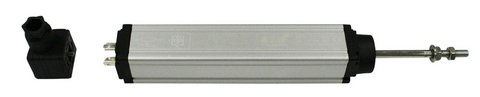
- Internal Position Feedback: Only feedback actuators with built-in potentiometric sensors work with these boards. Standard actuators without feedback cannot be synchronized.
- Identical Specifications: All actuators must share the same model number, stroke length, and force rating. Mixing different actuator types—even from the same manufacturer—will prevent proper synchronization.
- Matching Voltage: All actuators must operate at the same voltage (either all 12V or all 24V) and must match the supply voltage provided to the FA-SYNC-X board.
- Equal Mechanical Configuration: Actuators should have similar mounting configurations and mechanical advantages to ensure comparable load distribution.
The strict requirement for identical actuators stems from the need for consistent electrical characteristics in the feedback signals. Different actuator models produce different voltage curves across their stroke range, making accurate position comparison impossible when mixed.
Common Applications for Synchronized Systems
Synchronized multi-actuator systems appear across numerous industries and applications:
- Automotive and Marine: Tonneau covers, boat hatches, and convertible roof mechanisms require synchronized motion to prevent binding and ensure weathertight seals.
- Recreation Vehicles: RV slideouts, pop-up camper lifts, and roof extensions depend on synchronized actuators to maintain structural alignment.
- Industrial Automation: Material handling systems, adjustable workbenches, and manufacturing fixtures often use multiple actuators to position large or heavy loads.
- Renewable Energy: Solar tracking systems use synchronized actuators to adjust panel angles while maintaining precise alignment for maximum efficiency.
- Theatrical and Entertainment: Stage platforms, lighting rigs, and special effects equipment require synchronized movement for safety and precision.
Why Integrate Arduino with FA-SYNC-X Control Boards
While the FA-SYNC-X boards excel at maintaining synchronized actuator movement, they're designed for simple directional control via switches or remote controls. Integrating an Arduino microcontroller adds a powerful automation and logic layer without sacrificing the hardware-level synchronization benefits.
Enhanced Automation Capabilities
An Arduino-based control system enables sophisticated automation scenarios impossible with manual switching:
- Sensor-Based Automation: React to environmental conditions (light levels, temperature, proximity) to trigger actuator movement automatically.
- Timed Sequences: Program complex motion profiles with precise timing, delays, and conditional logic.
- User Interface Integration: Connect touchscreens, keypads, or wireless modules for advanced user control.
- Safety Interlocks: Implement emergency stops, limit checking, and operational safety logic in software.
- Data Logging: Record operational cycles, movement patterns, and system status for maintenance and analysis.

Simplified Development Compared to Pure Arduino Control
Developing a fully synchronized multi-actuator controller using only Arduino code presents significant technical challenges. You would need to implement real-time position monitoring, proportional motor control, load compensation algorithms, and failsafe mechanisms—all while maintaining microsecond-level timing precision. The FA-SYNC-X board handles these complex tasks in dedicated hardware, allowing your Arduino code to focus on higher-level application logic.
This division of responsibilities dramatically reduces code complexity, improves reliability, and shortens development time. Instead of hundreds of lines of synchronization code requiring extensive testing and tuning, your Arduino sketch can remain focused and maintainable.
Ideal Use Cases for Combined Control
The Arduino + FA-SYNC-X combination proves particularly valuable in these scenarios:
- Solar Tracking Systems: Automatically adjust panel angles throughout the day based on light sensor readings to maximize energy capture.
- Automated Greenhouse Vents: Open or close roof vents based on temperature and humidity sensors while maintaining synchronized movement.
- Smart Furniture: Create standing desks or adjustable beds with preset positions, scheduled movements, and occupancy detection.
- Security Applications: Automate gates, barriers, or protective covers based on access control systems or security sensors.
- Agricultural Automation: Control automated feeding systems, ventilation, or shade structures based on environmental conditions.
Hardware Setup and Calibration Process
Proper setup of the FA-SYNC-X board with your actuators forms the foundation for successful Arduino integration. This process must be completed before connecting any microcontroller.
Connecting Actuators to the FA-SYNC-X Board
The FA-SYNC-2 and FA-SYNC-4 boards feature either two or four 6-pin terminal blocks for actuator connections. Each terminal block accommodates one feedback actuator with the following wire connections:
- Motor Power (+): Positive motor supply
- Motor Ground (-): Negative motor supply
- Sensor Power (+): Feedback potentiometer positive supply (typically 5V from board)
- Sensor Ground (-): Feedback potentiometer ground reference
- Sensor Output 1: First wiper output from feedback potentiometer
- Sensor Output 2: Second wiper output (if applicable to actuator type)
Wire colors may vary between actuator models, so always consult your specific actuator's documentation for correct terminal identification. Incorrect wiring can damage both the actuator and control board.
Power Supply Connection
The FA-SYNC-X board receives power through a dedicated 2-pin terminal block located adjacent to the actuator terminal blocks. Critical requirements include:
- Voltage Match: Supply voltage (12V or 24V) must match your actuator specifications exactly.
- Polarity: Positive and negative terminals must connect correctly. Reversed polarity will cause immediate and permanent damage to the board.
- Current Capacity: Your power supply must provide sufficient current for all actuators operating simultaneously at maximum load, plus a 20-30% safety margin.
- Voltage Stability: Use a regulated power supply to prevent voltage sag during actuator operation, which can affect synchronization accuracy.
For current calculation, multiply the stall current of one actuator by the number of actuators, then add 30%. For example, four actuators rated at 3A stall current would require a power supply rated for at least 15.6A (4 × 3 × 1.3).
Initial Calibration Procedure
Before the FA-SYNC-X board can synchronize actuators, it must learn the feedback signal characteristics of your specific actuators. The calibration process involves:
- Initial Power-Up: Apply power to the board with all actuators connected. The status LED will indicate the board is uncalibrated.
- Full Extension: Manually trigger extension until all actuators reach full stroke. The board monitors and records maximum feedback voltage.
- Full Retraction: Manually trigger retraction until all actuators reach minimum stroke. The board records minimum feedback voltage.
- Calibration Lock: Follow the board's specific procedure (typically involving a button press sequence) to save calibration data.
Detailed calibration steps vary between FA-SYNC-2 and FA-SYNC-4 models, so always reference your board's user manual for exact procedures. Proper calibration ensures the board can accurately compare positions across all actuators throughout the full stroke range.
Interfacing Arduino with FA-SYNC-X Control Board
Once your FA-SYNC-X board is connected and calibrated to your actuators, integrating Arduino control requires addressing a key electrical compatibility challenge: the Arduino's 5V logic signals cannot directly drive the FA-SYNC-X board's control inputs, which require higher voltage to activate internal relays.
Understanding the Control Interface
The FA-SYNC-X board features a 2-pin control terminal block (typically the leftmost terminal block on the board) with two control inputs:
- Pin A (Extend): When connected to positive voltage (with Pin B grounded), actuators extend.
- Pin B (Retract): When connected to positive voltage (with Pin A grounded), actuators retract.
- Both Grounded (Stop): When both pins connect to ground, actuators stop and hold position.
This control scheme mirrors a standard DPDT (Double-Pole, Double-Throw) switch configuration used for reversible DC motor control. The board's internal circuitry uses these signals to control high-current motor drivers while maintaining synchronized position control.
Implementing Relay-Based Interface
To bridge the voltage gap between Arduino and FA-SYNC-X control inputs, we use two SPDT (Single-Pole, Double-Throw) relays as electrically isolated switches. This approach provides several advantages:
- Voltage Level Translation: Arduino's 5V signals control relay coils, while relay contacts switch the full system voltage.
- Electrical Isolation: Relays protect Arduino circuitry from voltage spikes and backfeed from motor circuits.
- Current Handling: Relays handle control currents that would exceed Arduino pin capabilities.
- Fail-Safe Operation: De-energized relays automatically connect control pins to ground (safe stop condition).
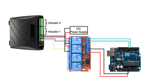
Detailed Wiring Configuration
The relay interface requires specific connections between Arduino, relay module, power supply, and FA-SYNC-X board:
Relay 1 (Extension Control):
- Coil Input: Connect to Arduino digital pin (e.g., pin 8) for control signal
- COM (Common) Terminal: Connect to FA-SYNC-X Pin A
- NO (Normally Open) Terminal: Connect to positive power supply terminal
- NC (Normally Closed) Terminal: Connect to negative power supply terminal (ground)
Relay 2 (Retraction Control):
- Coil Input: Connect to Arduino digital pin (e.g., pin 9) for control signal
- COM (Common) Terminal: Connect to FA-SYNC-X Pin B
- NO (Normally Open) Terminal: Connect to positive power supply terminal
- NC (Normally Closed) Terminal: Connect to negative power supply terminal (ground)
Relay Module Power:
- VCC: Connect to Arduino 5V output (if relay module current draw is acceptable) or external 5V supply
- GND: Connect to Arduino ground (common ground essential for signal reference)
Note: Many relay modules use active-low control (relay energizes when control pin goes LOW). Verify your specific relay module's trigger type and adjust code accordingly.
Choosing Appropriate Relay Modules
Relay modules designed for Arduino applications typically come in several configurations:
- Optocoupled Modules: Provide additional isolation between Arduino and relay circuits, recommended for industrial environments
- Active-High vs Active-Low: Ensure your code matches the relay trigger type (most common are active-low)
- Voltage Compatibility: Verify relay coils operate at 5V for direct Arduino connection
- Contact Ratings: Relay contacts should handle control current (typically under 1A for FA-SYNC-X inputs)
Arduino Programming and Control Logic
With hardware connections complete, implementing control software involves configuring digital outputs and creating functions to manage actuator direction. The code structure remains straightforward because the FA-SYNC-X board handles all synchronization complexity.
Basic Setup Configuration
Begin your Arduino sketch by defining pin assignments and initializing digital outputs:
// Pin definitions for relay control
const int RELAY_EXTEND = 8;  // Controls extension relay
const int RELAY_RETRACT = 9; // Controls retraction relay

void setup() {
  // Configure relay control pins as outputs
  pinMode(RELAY_EXTEND, OUTPUT);
  pinMode(RELAY_RETRACT, OUTPUT);

  // Initialize both relays to OFF (actuators stopped)
  // Note: Using HIGH for active-low relay modules
  digitalWrite(RELAY_EXTEND, HIGH);
  digitalWrite(RELAY_RETRACT, HIGH);
}
Directional Control Functions
Create dedicated functions for extend, retract, and stop operations to simplify your main program logic:
void extendActuators() {
  // Ensure retract relay is OFF
  digitalWrite(RELAY_RETRACT, HIGH);
  delay(50); // Brief delay prevents both relays energizing simultaneously

  // Activate extend relay (Pin A to positive voltage)
  digitalWrite(RELAY_EXTEND, LOW);
}

void retractActuators() {
  // Ensure extend relay is OFF
  digitalWrite(RELAY_EXTEND, HIGH);
  delay(50); // Brief delay prevents both relays energizing simultaneously

  // Activate retract relay (Pin B to positive voltage)
  digitalWrite(RELAY_RETRACT, LOW);
}

void stopActuators() {
  // Deactivate both relays (both control pins to ground)
  digitalWrite(RELAY_EXTEND, HIGH);
  digitalWrite(RELAY_RETRACT, HIGH);
}
The 50-millisecond delay between relay switches prevents both relays from being energized simultaneously, which would create a short circuit path through the power supply. This delay is especially important during direction changes.
Sensor-Based Automation Example
A practical implementation might use a light sensor to automate solar panel tracking:
const int LIGHT_SENSOR = A0;
const int LIGHT_THRESHOLD = 512; // Adjust based on sensor calibration

void loop() {
  int lightLevel = analogRead(LIGHT_SENSOR);

  if (lightLevel > LIGHT_THRESHOLD) {
    // High light level detected, extend panels toward sun
    extendActuators();
    delay(500); // Move for 500ms
    stopActuators();
    delay(5000); // Wait 5 seconds before next check
  } else {
    // Low light level, retract panels to home position
    retractActuators();
    delay(500); // Move for 500ms
    stopActuators();
    delay(5000); // Wait 5 seconds before next check
  }
}
Timed Sequence Example
For applications requiring preset positions or timed movements:
void loop() {
  // Extend to full stroke
  extendActuators();
  delay(10000); // Run for 10 seconds (adjust based on actuator speed)
  stopActuators();

  // Hold extended position
  delay(30000); // Wait 30 seconds

  // Retract to home position
  retractActuators();
  delay(10000); // Run for 10 seconds
  stopActuators();

  // Hold retracted position
  delay(30000); // Wait 30 seconds
}
Safety Considerations in Code
Implement these safety practices in your Arduino code:
- Mutual Exclusion: Never allow both extend and retract commands simultaneously
- Movement Delays: Always include brief delays when changing directions to prevent relay overlap
- Timeout Protection: Implement maximum runtime limits to prevent over-extension if limit switches fail
- Emergency Stop: Consider adding a hardware interrupt pin for immediate stop capability
- Startup State: Always initialize to stopped state during setup()
Limitations and Practical Workarounds
While the Arduino + FA-SYNC-X combination provides powerful capabilities, understanding its limitations allows you to design effective workarounds when necessary.
Position Feedback Limitation
The most significant limitation is that Arduino cannot directly read actuator position. The FA-SYNC-X board receives and processes all feedback signals internally but doesn't share position data with external controllers. This creates challenges for applications requiring precise intermediate positioning or closed-loop control based on actuator position.
Time-Based Position Estimation
For applications not requiring absolute precision, you can estimate actuator position using time-based calculations:
// Actuator specifications
const int STROKE_LENGTH_MM = 200; // 200mm stroke
const int EXTENSION_TIME_MS = 20000; // 20 seconds full stroke
const float MM_PER_MS = (float)STROKE_LENGTH_MM / EXTENSION_TIME_MS;

// Position tracking variables
unsigned long movementStartTime = 0;
int estimatedPosition = 0; // 0 = retracted, STROKE_LENGTH_MM = extended
bool isMoving = false;

void extendWithTracking() {
  if (!isMoving) {
    movementStartTime = millis();
    isMoving = true;
  }
  extendActuators();
}

void updatePositionEstimate() {
  if (isMoving) {
    unsigned long elapsed = millis() - movementStartTime;
    estimatedPosition = constrain(elapsed * MM_PER_MS, 0, STROKE_LENGTH_MM);
  }
}
This approach provides reasonable accuracy for applications like automated furniture or access control, where being within 5-10mm of target position is acceptable. However, accuracy degrades over time due to load variations, temperature effects on motor speed, and voltage fluctuations.
External Position Feedback Implementation
For applications demanding precise position control, adding external feedback sensors provides Arduino-accessible position data:
Linear Potentiometer Integration:
- Mount a linear potentiometer parallel to actuator stroke
- Connect potentiometer wiper to Arduino analog input
- Connect potentiometer ends to Arduino 5V and GND
- Read position directly via analogRead()
- Calibrate min/max values to stroke endpoints
Ultrasonic Distance Sensor:
- Position sensor to measure distance to moving load
- Calculate actuator extension from distance changes
- Useful for indirect measurement when direct mounting isn't possible
Rotary Encoder on Pulley System:
- Attach cable from actuator to spring-loaded pulley with encoder
- Count encoder pulses to track linear movement
- Provides high precision but requires mechanical design
Implementing Closed-Loop Control with External Feedback
const int POSITION_SENSOR = A1;
int targetPosition = 512; // Middle position (0-1023 range)
int currentPosition = 0;
const int TOLERANCE = 10; // Acceptable position error

void loop() {
  currentPosition = analogRead(POSITION_SENSOR);

  if (currentPosition < targetPosition - TOLERANCE) {
    // Below target, extend
    extendActuators();
  } else if (currentPosition > targetPosition + TOLERANCE) {
    // Above target, retract
    retractActuators();
  } else {
    // Within tolerance, stop
    stopActuators();
  }

  delay(50); // Update rate
}
Multi-Position Presets Without Feedback
For applications like adjustable standing desks or TV lifts with preset positions, you can implement a calibration routine that records movement times between positions:
// Preset positions (time in milliseconds from home)
const unsigned long POSITION_1 = 0;      // Home position
const unsigned long POSITION_2 = 5000;   // 5 seconds from home
const unsigned long POSITION_3 = 10000;  // 10 seconds from home
const unsigned long POSITION_4 = 15000;  // 15 seconds from home

void moveToPreset(unsigned long targetTime) {
  // First, return to home position
  retractActuators();
  delay(20000); // Full retraction time
  stopActuators();
  delay(500);

  // Then extend to target
  if (targetTime > 0) {
    extendActuators();
    delay(targetTime);
    stopActuators();
  }
}
Troubleshooting Common Issues
Actuators Not Responding to Arduino Commands
- Check relay operation: Verify relays click when Arduino pins change state (use LED indicators if relays are enclosed)
- Verify relay wiring: Confirm COM, NO, and NC terminals connect correctly
- Test relay logic level: Some relay modules require active-high signals; adjust code if yours differs
- Measure control voltages: Use multimeter to verify voltage appears on FA-SYNC-X control pins when relays activate
- Check common ground: Arduino and relay module must share ground connection
Intermittent or Erratic Operation
- Power supply capacity: Insufficient current causes voltage sag during actuator startup, affecting both actuators and control electronics
- Loose connections: Vibration from actuator operation can loosen terminal block connections over time
- Relay contact degradation: High-current switching eventually damages relay contacts; replace relay modules periodically
- EMI interference: Actuator motor noise can interfere with Arduino signals; use shielded cables and add capacitors across motor terminals
Loss of Synchronization
- Recalibrate FA-SYNC-X: If actuators drift out of sync, repeat the calibration procedure
- Verify actuator compatibility: Confirm all actuators are truly identical models with same specifications
- Check feedback connections: Damaged or loose feedback wires prevent proper synchronization
- Inspect mechanical systems: Binding, misalignment, or unequal loads can exceed synchronization capabilities
Code Debugging Techniques
- Serial monitoring: Add Serial.print() statements to track program flow and variable values
- LED indicators: Connect LEDs to relay control pins to visualize command signals
- Simplified testing: Test extend, retract, and stop functions independently before implementing complex logic
- Timing verification: Use millis() to log actual movement durations and compare to expected values
Advanced Implementation Strategies
Wireless Control Integration
Adding wireless capabilities expands control possibilities significantly:
- Bluetooth Control: HC-05 or HC-06 modules enable smartphone control via custom apps or terminal applications
- WiFi Integration: ESP8266 or ESP32 modules allow web-based control, IoT integration, and remote monitoring
- RF Remote: 433MHz or 2.4GHz receiver modules enable dedicated wireless remote controls
- LoRa Communication: For long-range outdoor applications like agricultural automation
Multi-Sensor Automation Systems
Combine multiple sensor types for sophisticated automation:
- Weather Stations: Retract awnings or close vents based on rain sensors, wind speed, and temperature
- Occupancy Detection: Adjust furniture or access systems based on PIR sensors or ultrasonic presence detection


