Every child deserves the freedom to play, explore, and experience the simple joy of driving around the neighborhood with friends. For children with mobility challenges like cerebral palsy, that independence often remains out of reach — until engineering and compassion converge to create something remarkable. This comprehensive guide chronicles the design and construction of a remote-controlled Power Wheels vehicle specifically adapted for a child with limited motor control, transforming what would typically be an inaccessible toy into an empowering mobility platform.
🎥 Video — How to make an RC Power Wheels for a Disabled Child
This project represents more than a technical modification; it's an exercise in assistive technology development that demonstrates how electric linear actuation systems, precision motor controls, and thoughtful design can restore agency to children who face physical limitations. The conversion replaces manual steering and throttle control with a parent-operated RC system while maintaining the authentic driving experience for the child passenger. The result is a fully functional, weather-resistant vehicle that allows independent play — with remote oversight for safety.
What follows is a detailed technical guide covering electrical system redesign, linear actuator integration for steering automation, motor control calibration, LED lighting installation, and comprehensive weatherproofing. While this is an advanced build requiring electrical knowledge, fabrication skills, and approximately $1,000 in components, it's achievable for determined builders willing to invest the time to give a child an extraordinary gift.

Project Overview and Requirements
This build centers on converting a Power Wheels Tough Talkin' Jeep Wrangler into a remotely operated vehicle suitable for a child with cerebral palsy. The original vehicle relies on direct physical control — a foot pedal for acceleration and manual steering wheel manipulation. Children with spastic motor control or limited limb coordination cannot operate these systems reliably, making standard Power Wheels vehicles inaccessible despite their appeal.
The engineering solution involves three primary system modifications: replacing manual steering with electronically controlled linear actuation, substituting the foot pedal throttle with an electronic speed controller (ESC) responsive to RC input, and installing a dual-battery power system to independently supply high-current motor demands and lower-current accessory loads. Additionally, the build incorporates therapeutic elements, including an optional foot-activated light switch that provides motor skill development incentive through immediate visual feedback.
Understanding the scope is critical before beginning. This is not a weekend project or simple electronics swap. Expect 30-40 hours of fabrication, wiring, calibration, and testing time spread across multiple sessions. The complexity rivals automotive aftermarket installations, requiring methodical attention to polarity, circuit protection, waterproofing, and system integration. Budget expectations should account for not just component costs but also specialty tools like quality wire crimpers, heat shrink equipment, and multimeter diagnostics.
Essential Components and Tools
Core Electrical Components
The heart of this conversion consists of several specialized electronic control systems. The Mamba Max Pro ESC serves as the interface between RC receiver and the vehicle's brushed DC motors, providing smooth acceleration, regenerative braking, and proportional speed control far superior to the original on/off foot pedal system. This ESC is designed for RC vehicles and includes a built-in Battery Eliminator Circuit (BEC) that outputs regulated 5V power to the receiver, eliminating the need for a separate receiver battery.
Steering automation relies on a FIRGELLI linear actuator paired with the LAC board controller. The actuator provides the mechanical force to push and pull the steering linkage, while the LAC board translates RC servo signals into precise position control with built-in feedback. This closed-loop system ensures accurate steering response and prevents mechanical binding through adjustable limit settings and speed control. The actuator's 2-inch stroke provides sufficient throw to achieve full steering lock without exceeding the vehicle's mechanical constraints.
The FlySky FS-GT3B or equivalent 3-channel RC transmitter and receiver complete the control system. Channel 1 manages steering (left/right actuator control), Channel 2 controls throttle and direction (forward/reverse motor control), and Channel 3 remains available for future expansion like auxiliary lighting or sound effects. The system operates on 2.4GHz frequency, providing interference-free operation with approximately 100-meter range — more than adequate for supervised neighborhood use.
Power System Components
A dual-battery architecture separates high-current motor loads from sensitive electronics and accessories. The primary aftermarket 12V 12Ah sealed lead-acid (SLA) battery powers the drive motors through the ESC. The higher amp-hour rating compared to the stock 9.5Ah battery extends runtime, while the increased capacity helps prevent voltage sag during peak acceleration. An inline 30-amp fuse protects the motor circuit from short-circuit conditions.
The secondary battery — the original Power Wheels 12V 9.5Ah unit — operates the linear actuator, LED lighting systems, and accessory circuits. This separation prevents motor current spikes from disrupting actuator position control and ensures predictable lighting performance. A marine-grade switch panel with integrated 10-amp circuit breakers provides independent control over the charger connection, running lights, pedal-activated lights, and actuator power.
Both batteries require individual charging systems. The motor battery connects to a Schumacher 300 onboard charger capable of 3-amp output, while the accessory battery uses the original Power Wheels wall charger outputting 1.5 amps. The charging rate should not exceed 25% of battery amp-hour capacity to prevent overheating and extend battery life. Battery Tender-style harnesses with inline 7.5-amp fuses provide quick-connect charging ports.

Fabrication and Installation Tools
Successful completion requires both standard hand tools and several specialty items. Electrical work demands quality wire strippers, ratcheting crimpers for insulated terminals, and a butane torch or heat gun for activating heat-shrink connections. A soldering iron with 60/40 rosin-core solder is essential for the Castle Creations bullet connectors that attach motors to the ESC — these high-current connections must be soldered, not crimped.
Drilling and cutting operations require variable-speed drills with bits ranging from 1/8-inch to 3/4-inch, plus Forstner bits for clean holes through the Jeep's plastic body. A razor knife with fresh blades handles plastic cutting tasks, while a Dremel rotary tool or equivalent proves invaluable for grinding, cutting, and deburring operations. If fabricating custom headlight lenses, a scroll saw and belt sander streamline the shaping process.
Diagnostic equipment should include a quality digital multimeter for voltage verification, continuity testing, and troubleshooting. The Castle Link USB adapter (free with code inside the ESC box) allows computer-based ESC programming, though the Field Card programmer provides an alternative for $10 that doesn't require a laptop at the workbench.
Deconstruction and Preparation
Initial Function Testing
Before any modification begins, verify the base vehicle's functionality. Assemble only the battery compartment and install the included battery. Connect the battery harness and test that both rear wheels spin freely when the foot pedal is depressed. This baseline test confirms the motors, gearboxes, and original wiring are functional before substantial modification makes warranty claims or simple troubleshooting impossible.
If motors fail to operate, charge the battery for the recommended 18 hours before drawing conclusions. Dead batteries are the most common "defect" in new Power Wheels vehicles. Should charging not resolve the issue, contact the manufacturer for replacement before proceeding further. Once functionality is confirmed, disconnect and remove the battery for charging while proceeding with disassembly.

Removing Original Controls
The factory control system consists of a mechanical steering linkage and an electrical foot pedal switch that completes the motor circuit. Begin by removing the plastic wire channel covering from under the vehicle and extracting the foot pedal assembly using flat-head screwdrivers to release the retaining tabs. Disassemble the pedal mechanism carefully, preserving all components — the foot switch will be repurposed as a therapeutic exercise device to activate accessory lighting.
Next, remove the dashboard-mounted shift control assembly. Despite appearing functional, this unit simply houses two switches that connect to the pedal assembly to provide high/low speed selection and forward/reverse direction. Remove the six screws securing the housing, extract the switches and their wiring harnesses, then reassemble the empty housing and reinstall it for appearance. The vehicle will look stock from the driver's seat even though controls are inoperative.
The steering system requires partial disablement rather than complete removal. The steering wheel connects to the front wheels via a metal rod with flared tabs that engage the wheel assembly. Using a bench grinder or rotary tool, carefully grind off these engagement tabs while leaving the rod itself intact. This allows the steering wheel to remain in position (providing a handhold and maintaining stock appearance) while decoupling it from the wheels, which will now be controlled by the linear actuator.
Motor Circuit Preparation
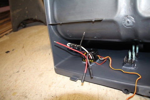
The original wiring uses color-coded pairs — orange/blue for one motor, red/black for the other — that connect through quick-disconnect blocks to the foot pedal switch. Cut these wires at the switch housings and strip back 1/4-inch of insulation. Mark polarity clearly: orange and red are positive, blue and black are negative. These designations become critical during subsequent parallel wiring and ESC connection.
A critical error occurs when motors are simply wired in parallel without accounting for their opposing physical orientation. Both motors must rotate in the same relative direction to produce forward motion, but because they mount facing opposite directions, their electrical polarity must be reversed relative to each other. Test this by temporarily connecting both motors' positive leads together and both negative leads together, then briefly touching them to the battery. One wheel should spin forward, the other backward, indicating an error.
Correct this by reversing polarity on one motor — swap its positive and negative connections. When retested, both wheels should now spin in the forward direction. Create Y-harnesses using scavenged quick-connect terminals or quality heat-shrink butt splices to parallel the corrected motor pairs into single positive and negative leads. These will connect to the ESC's motor output wires using Castle Creations bullet connectors that must be soldered for reliable high-current handling.

Linear Actuator Steering System
Actuator Mounting and Mechanical Connection
The linear actuator must mount rigidly to the vehicle chassis in a position where its stroke can effectively push and pull the steering linkage through its full range of motion. Location is typically in the front battery compartment area, positioned beneath or alongside the steering bar with the actuator body secured to prevent movement during operation. Cut away plastic support tabs as necessary to achieve proper clearance and alignment.
Mounting involves multiple securing methods for redundancy. Silicone adhesive provides initial positioning and some vibration damping, but cannot be relied upon as the sole attachment under the lateral loads steering generates. Stainless steel hose clamps wrapped around the actuator body and passed through holes drilled into the battery compartment provide mechanical retention. Insert PVC spacers between the actuator and strap to maintain even clamping pressure and prevent deformation of either component.
Drill a 3/4-inch wire passage hole through the battery compartment floor where the actuator's electrical leads exit, positioning it to minimize wire strain. The connection between actuator rod and steering linkage requires careful engineering — the initial build used a stainless steel bolt that sheared after four hours of testing due to inadequate tensile strength and off-axis loading. The successful solution employed a door hinge cut in half, with Grade 5 bolts connecting actuator to hinge and Grade 8 bolts connecting hinge to steering bar, plus a self-tapping screw preventing hinge rotation under torque.

LAC Board Wiring and Configuration
The LAC (Linear Actuator Control) board serves as the interface between RC servo signals and the actuator's motor and feedback systems. Proper wiring is non-intuitive and poorly documented, making careful attention to the following procedure essential. The board requires three separate connections: power input, RC signal input, and actuator motor/feedback connections.
Power arrives via the X6 terminal block: positive (red or white) to the + terminal, negative (black) to the - terminal. This power comes from the accessory battery through the marine switch panel, providing 12V to drive the actuator motor. Critically, do NOT connect power to the battery terminal of the RC receiver cable — the LAC board is powered externally, not through the RC system's 5V supply which would be insufficient.

The RC signal connection uses a standard servo extension cable with the center power wire cut. This wire (typically red or orange) would normally supply 5V power from receiver to servo, but since the LAC board has its own power supply, connecting this wire creates a conflict that can damage components. Cut the center wire cleanly, insulate the cut ends with heat shrink, and connect the remaining signal (white or yellow) and ground (black or brown) wires to the X3 terminal: ground to -, signal to RC.
The actuator's five-wire connection terminates at the X4 block in the following order from top to bottom: white (P+), yellow (P), red (M+), black (M-), and blue (P-). Note that some FIRGELLI documentation shows blue and white reversed — this is an error in their diagrams. Verify your wiring matches the correct sequence or the actuator will not respond to RC input. Use ferrules or carefully tinned wire ends for secure terminal block connections.

Running Cables Between Compartments
With the LAC board mounted in the front battery compartment and the RC receiver installed in the rear seat area, a cable run of approximately 36-48 inches is required. Chain multiple servo extension cables together using male-to-male adapters where necessary. The connection from LAC board to first extension is male-to-male (both board and extension have male connectors), while subsequent extensions use standard male-to-female configuration.
Protect this cable run from abrasion and moisture using 1/2-inch electrical PVC conduit secured to the vehicle's underside with mounting brackets. Include 90-degree elbows where the cable enters and exits compartments. While you technically only need to cut the center power wire on the first extension segment, it's harmless to leave subsequent segments intact — the dead wire provides additional mechanical strength without electrical consequences.

Electronic Speed Controller Integration
Motor Connections and Power Routing
The Mamba Max Pro ESC outputs three wires to the motor: red (positive), black (negative), and white (auxiliary, unused for brushed motor applications). Connect your paralleled motor harness to the red and black leads using the included Castle Creations bullet connectors — these must be soldered, not crimped, to handle the sustained 20-30 amp current draw during acceleration and climbing. Use quality 60/40 rosin-core solder and ensure connections are mechanically sound before soldering to prevent cold joints.
Input power to the ESC arrives from the 12V 12Ah motor battery through an inline 30-amp fuse holder. Use 12-gauge wire for this connection to minimize voltage drop and heat generation. The positive lead runs through the fuse, while the negative lead connects directly to battery ground. Install the inline fuse within six inches of the battery positive terminal for optimal circuit protection — this placement ensures any short circuit downstream of the fuse will trip protection before affecting the battery.
Add a power switch (salvaged from the original shift control mechanism works well) between the ESC and battery to enable complete system shutdown without disconnecting battery terminals. This switch allows safe charging of the motor battery while ensuring no power reaches the motors or ESC. Install a small LED indicator in parallel with the switch to provide visual confirmation of power state.

ESC Programming for Brushed Motors
Out of the box, the Mamba Max Pro is configured for brushless sensored motors, making it incompatible with Power Wheels brushed motors. Reconfiguration requires either the Castle Link USB adapter (free with mail-in code) paired with their Windows/Mac software, or the Field Card programmer ($10 with mail-in code) that operates standalone. The Field Card approach is recommended for builders without ready computer access at their workspace.
Connect the Field Card to the ESC's receiver lead with power applied to the ESC. The card enters programming mode, displaying current settings via numbered LEDs. Navigate through settings using the single push-button interface: short press advances to the next parameter, long press cycles through available values for the current parameter. Configure the following critical settings:
- Motor Type: Brushed (this is the most critical setting)
- Brake/Reverse Type: Forward/Brake/Reverse (Setting 3)
- Brake Amount: 50% (Setting 2 — provides smooth stopping without harsh deceleration)
- Reverse Amount: 50% (Setting 2 — limits reverse speed to safe levels)
- Punch/Traction Control: Lowest setting (Setting 4 — prevents wheel spin and provides smooth acceleration)
- Drag Brake: 10% (Setting 2 — provides slight braking when throttle is neutral, reducing rolling)
- Low Voltage Cutoff: 5V (prevents battery over-discharge)
- Motor Timing: Normal (default setting)
After programming, cycle power to the ESC and verify it no longer produces the startup error tones that indicate brushless configuration. The system should initialize with a simple ready tone sequence. Do not attempt motor operation yet — RC transmitter calibration must occur first.

RC Receiver Installation and Integration
Receiver Mounting and Antenna Placement
The FlySky receiver measures approximately 2.5 x 1.5 x 0.5 inches and mounts inside the vehicle's rear seat compartment for optimal antenna positioning and protection from weather. Drill a small hole through the seat back to route the antenna wire externally — antenna performance degrades significantly when fully enclosed in plastic or metal. Secure the antenna strain relief to the seat exterior with silicone adhesive, allowing the antenna wire to hang freely without sharp bends.
Mount the receiver itself to the interior seat surface using closed-cell foam tape or additional silicone adhesive. Initial attempts with silicone alone proved insufficient as the material peels from the smooth plastic over time. A small plastic strap or zip-tie provides more reliable long-term retention. Position the receiver to allow easy access to the three channel ports while keeping wire runs to the ESC and LAC board extensions as short and direct as possible.

Channel Assignments and Connections
The receiver provides four ports: one for optional battery power (unused in this build) and three for control channels. Channel assignments are as follows:
- Channel 1 (Steering): Connect the servo extension cable from the LAC board. This channel responds to the steering wheel on the transmitter and controls left/right actuator movement.
- Channel 2 (Throttle): Connect the ESC's receiver lead. This channel responds to the trigger on the transmitter and controls forward/reverse motor operation. The ESC's built-in BEC provides 5V power to the receiver through this connection.
- Channel 3: Unused — available for future expansion such as sound modules, additional lighting controls, or auxiliary functions.
- Battery Port: Unused — the ESC's BEC supplies all necessary receiver power. Do NOT connect an external battery or BEC to this port, as doing so creates a power conflict that can damage the receiver or ESC.
Observe proper polarity when connecting cables. Standard servo cables use black or brown for ground (-), red or orange for power (+), and white or yellow for signal. Most connectors are keyed to prevent reverse insertion, but double-check orientation before applying power. An improperly connected receiver will either fail to respond or produce erratic control behavior.

Dual Battery Power Distribution
Accessory Battery Wiring Architecture
The original Power Wheels battery supplies power to all accessory systems: linear actuator, LED lighting, and optional pedal-activated lights. This separation from the motor battery prevents voltage sag during acceleration from disrupting actuator position control or dimming lights. The distribution system centers on a four-switch marine control panel that provides individual circuit control and integrated 10-amp overcurrent protection.
Wire the control panel for parallel operation across switches 2-4, with switch 1 operating independently. Connect the battery positive lead to the panel's common positive bus, and negative to the common negative bus. This provides switched 12V to all four circuits. However, to prevent the battery charger from back-feeding into accessory circuits (which slowly drains the battery when the charger is off), isolate switch 1 by cutting the parallel positive connection and running dedicated positive and negative leads from the battery to this switch.

Switch assignments are as follows:
- Switch 1 (Charger): Controls connection between battery and onboard charger input. Turn on only during charging, off during operation.
- Switch 2 (Running Lights): Powers headlights and tail lights through the parallel bus.
- Switch 3 (Pedal Lights): Powers the roll bar and bumper lights through the foot pedal switch for therapeutic activation.
- Switch 4 (12V Power): Supplies power to the LAC board and linear actuator for steering control.
Use a grounding bar (available at auto parts stores) to consolidate all negative returns from accessory circuits. This simplifies wiring by eliminating multiple splices and provides a single secure connection point to battery negative. Route all negative leads — from lighting circuits, LAC board, and charger — to the grounding bar, then run a single heavy-gauge wire from the bar to the battery.
Control Panel Installation
The marine switch panel measures approximately 6 x 6 inches and requires a flat mounting surface with access to the rear for wiring. The back of the vehicle's seat provides an ideal location — the seat is hollow molded plastic, allowing wire runs to be concealed inside while the rear surface provides a weatherproof mounting plane. Cut an opening through the seat back using a sharp razor blade in multiple passes (the thick plastic will not cut in a single pass).
Apply a continuous bead of silicone sealant to the panel's mounting flange before installing. This creates a weather-tight seal preventing rain intrusion into the seat cavity where electrical connections reside. Secure the panel with the provided screws, wipe away excess silicone squeeze-out, and allow 24 hours to cure before stress-testing the installation. Label each switch with weatherproof vinyl labels or a label maker for operational clarity.

Motor Battery Installation
The larger 12V 12Ah aftermarket battery replaces the original Power Wheels battery in the front compartment. Most aftermarket SLA batteries lack the integrated fuse found in OEM Power Wheels batteries, necessitating external fusing. Install the 30-amp inline fuse holder within six inches of the battery positive terminal, then run 12-gauge wire to the main ESC power switch salvaged from the shift control assembly.
Secure the battery with additional strapping beyond the vehicle's original retention system. The aftermarket battery may be physically larger than the OEM unit, potentially creating clearance issues or allowing movement during operation. Use adjustable hose clamps or nylon straps to cinch the battery firmly in place. Insert PVC spacers as necessary to fill gaps and prevent lateral shifting. An unsecured battery risks terminal damage from movement and creates a significant safety hazard should a terminal short against the vehicle chassis.
Install a Battery Tender-style quick-connect harness with integrated 7.5-amp fuse for charging. This harness remains permanently connected to the battery, with the mating connector routed to an accessible location outside the battery compartment. A second salvaged switch controls this charging connection, allowing complete isolation when the vehicle is in use. This prevents the charger from drawing minimal parasitic current that can discharge the battery over extended storage periods.


