

12 Volt Double-Pole Double-Throw Relay (DPDT)


")

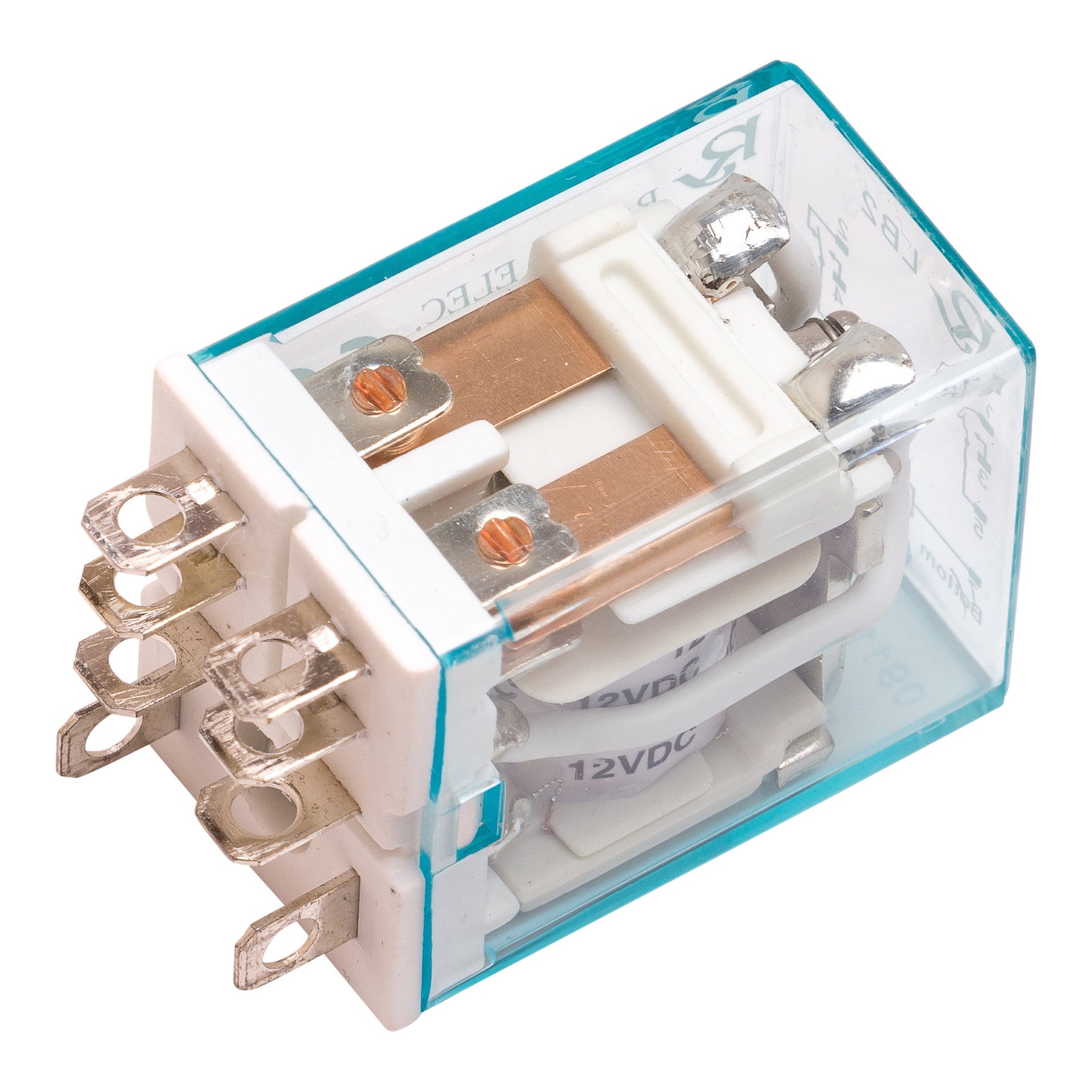
12 Volt Double-Pole Double-Throw Relay (DPDT)
Description
This compact 12V DPDT (Double-Pole Double-Throw) relay is a versatile switching device commonly used in automation, motor control, robotics, automotive systems, and actuator applications. Despite its small size, it provides powerful control capabilities, including the ability to reverse the polarity of a DC motor or linear actuator.
A DPDT relay uses an electromagnetic coil to electrically isolate a low-voltage control circuit from a higher-power load circuit. When the relay is energized, its internal contacts switch positions, allowing you to safely control motors, actuators, lights, solenoids, and other electrical devices.
One of the most common applications for a DPDT relay is reversing the direction of an Actuator or DC motor. By changing the polarity applied to the motor terminals, the relay can switch the motor's rotation from clockwise to counterclockwise. When the relay is in its default state, the motor operates in one direction. When the relay coil is energized, the contacts change position, reversing the polarity and causing the motor to rotate in the opposite direction.
Features
- Operates on a 12V DC control signal
- Double-Pole Double-Throw (DPDT) contact configuration
- Ideal for reversing DC motor and linear actuator direction
- Electrically isolates control and load circuits
- Compact design for easy integration into projects
- Suitable for automotive, industrial, robotics, and automation applications
Whether you're controlling a linear actuator, building an automation system, or designing a custom motor control circuit, this 12V DPDT relay provides a simple and reliable switching solution.
Works with our Connecting interface connector FA-LB2-12DS
Specifications
- 50/60Hz
- 12A 30VDC
- UL, CUL, TUV and CE approved
- "FA-LB2-12DS-SS" Socket available for easy installation
- For DPDT Timer relay controller click here
- For non-timer SPDT relay click here
Technical Drawing

