


We have a huge selection of Linear Actuators to suit all applications and industries. So what is a Linear Actuator?. They are devices that convert the rotational motion of an electric motor into linear motion – that is, it will provide both push and pull movements where the force is related to the power of the motor and the gear ratio used.
When Actuators create pushing and pulling forces, it is possible to lift, drop, slide, adjust, tilt, push or pull any object simply by pushing a button.
Additionally, Linear Actuators provide a safe and clean movement with accurate motion control that you have full control over. They are energy efficient and have a long lifetime with little or no maintenance required. Read our Blog post Linear Actuators 101 to learn more in greater detail
How do linear actuators work?
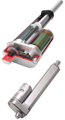
The Linear motion is created by using a screw or Lead-screw that turns either clockwise or counter-clock-wise and this causes the shaft to extend and retract. This principle is basically a nut on the screw to move up and down the screw as the lead-screw turns. This is what creates the linear motion.
The motors used are either AC or DC powered, most however run on 12v dc, but other voltages are optional. To make the Actuator go the other direction you simple reverse the wires from the Actuator (reverse polarity) from the actuator controller or power supply. This is typically done through a switch that automatically reverses the polarity to the motor for you.
Firgelli created a Technical article you can visit here to read. How do linear actuators work?
What are the different types of Actuators?
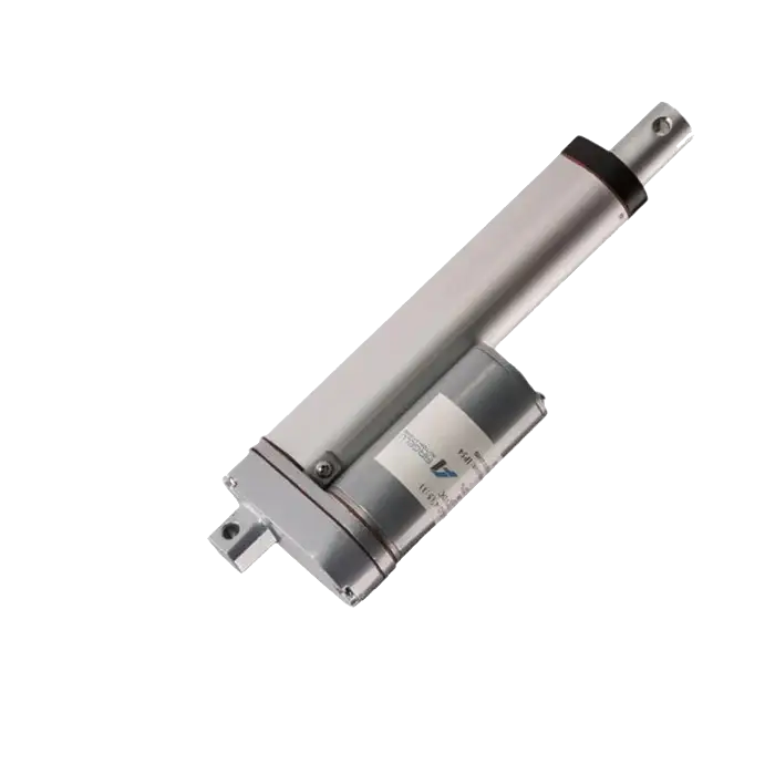
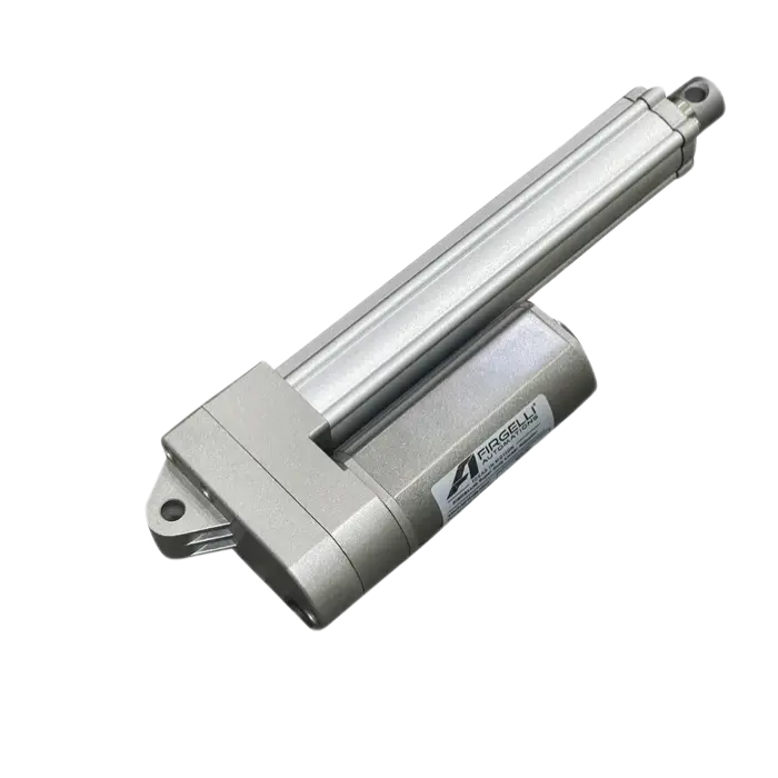
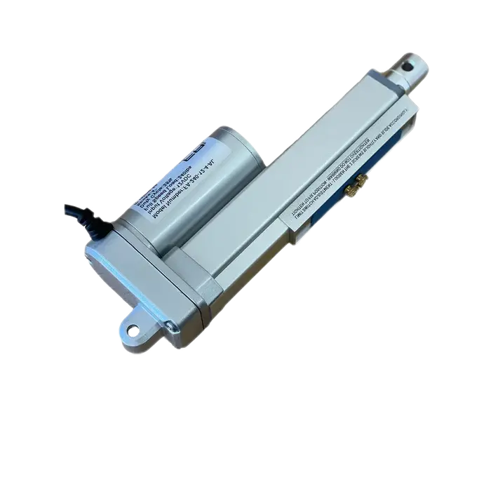
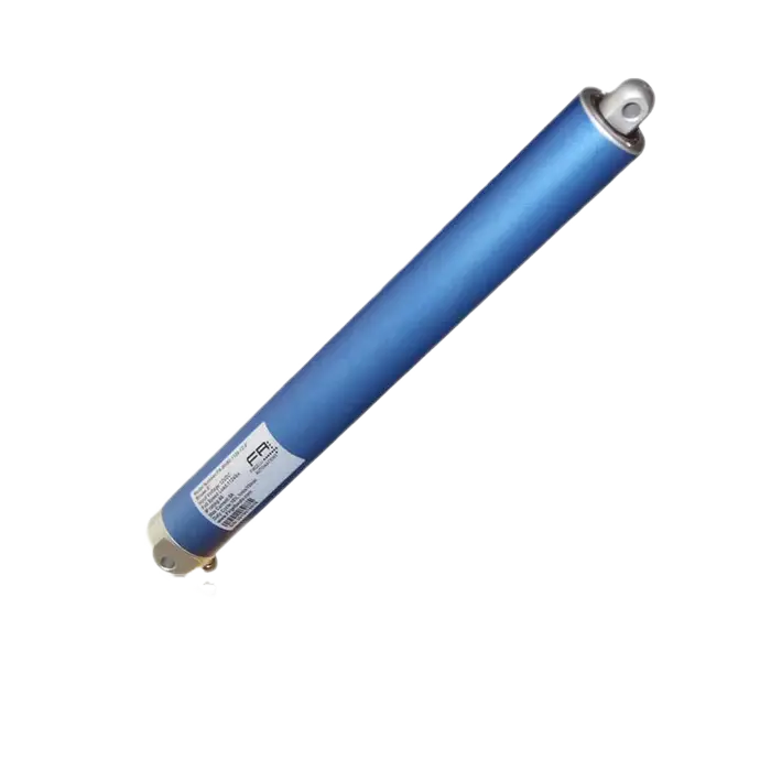
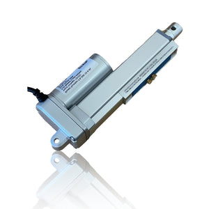
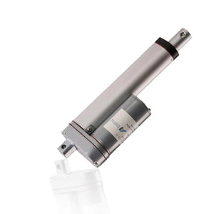
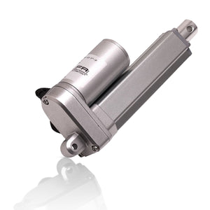
There are many different types sizes and styles of Linear Actuators. the Most common type is a Rod style where a Rod shaft slides in and out of the body. These create the linear motion required to be called a Linear Actuator. Other types include, Track Actuators, Column Actuators, and within each type there will be different control methods. For more detail read our Blog posts titled Types of Electric Linear Actuators. Actuators also vary in their ip-rating. Actuators working in harsh environments require a certain ip-rating. Be sure to check out our ip-rating article to learn more.